
Design for CNC machining by matching the part's dominant geometry to the process, creating stable workholding surfaces, allowing short rigid tools to reach each feature and limiting tight tolerances and fine finishes to functional interfaces. Review the material, blank, heat treatment and coating as part of the same route. There is no reliable universal minimum wall, pocket ratio or hole depth: practical limits depend on material, feature size, tool diameter, access, machine, workholding, quantity and required accuracy.
A CNC machining design guide is useful only if it helps a designer make decisions before a quote turns into a production problem. The goal is not to simplify every component into a block. It is to identify geometry that drives special tooling, extra orientations, weak workholding, long measurement cycles or unpredictable distortion—and then decide whether that complexity serves the product.
NIST describes conceptual process planning as an early design activity for evaluating manufacturability and manufacturing cost. Its design-for-cost research makes the same timing point: design adjustments are easier to negotiate before production is commissioned. A DFM review therefore belongs between functional definition and final RFQ, while the designer can still distinguish a necessary feature from a modeling habit.

01 · PurposeUse DFM to expose manufacturing consequences
Design for manufacturability does not give the supplier permission to change function. It creates a structured conversation about how design intent will become a process plan. A useful review separates three categories:
Do not ask only, “Can you make it?” A capable supplier can sometimes produce difficult geometry with long-reach tools, custom fixtures, electrical discharge machining, special inspection or several setups. The more useful questions are: What creates risk? Which requirement creates that risk? What alternatives preserve function? What changes between prototype and production?
Keep the answer tied to the controlled drawing and model. NIST's model-based enterprise review focuses on the cost and losses associated with inadequate design and production information. A polished CAD solid is not enough if datums, tolerances, material condition, finish and revision authority remain unclear.
02 · Route selectionLet the dominant geometry suggest the process
Start by hiding small holes, chamfers and markings. Look at the body that remains. A shaft, sleeve, piston or ring organized around one centerline is usually turning-led. A bracket, plate, manifold or housing organized around faces and pockets is usually milling-led. A round body with cross holes, flats or an off-axis pattern may justify a combined route.
The CNC milling versus turning guide explains this choice in detail. For DFM, the important point is that the selected route changes how the part is held and which relationships are easiest to maintain in one setup.
| Design signal | Likely process implication | DFM question |
|---|---|---|
| Most critical diameters share one axis | Turning can keep concentric features in a spindle-based setup | Can secondary flats or holes be made with live tooling or a planned second setup? |
| Critical features lie on several faces | Milling or indexed machining controls face-to-face relationships | Can orientations be reduced without hiding a functional surface? |
| Cast or forged housing with selected machined pads | Blank variation and stock allowance affect location | Which as-cast features must relate to the machined datum system? |
| Deep central bore with external prismatic features | A combined boring, turning or milling sequence may be needed | Which feature defines the primary axis and inspection setup? |
| Features accessible from opposite sides | Part turnover or multi-axis access may be required | Can a common datum be maintained through the transfer? |
Do not specify a machine type merely because it sounds more advanced. A five-axis machine does not automatically make every multi-face part cheaper. Programming, tool access, fixturing, cycle time, batch size and available inspection still matter. Define the outcome, then let suppliers explain the proposed route and its assumptions.
03 · WorkholdingGive the process a stable way to locate and clamp the part
Every cutting force reacts through the workpiece and fixture. If the part has no stable locating surfaces, the process may need soft jaws, sacrificial tabs, custom nests or an intermediate operation that creates datums before critical machining begins.
Review the first and last setup
The first setup must hold raw stock or a variable casting. The final setup may have very little material left for clamping. A design that looks accessible in finished form can be difficult to produce because the intended gripping region disappears halfway through the process.
- Identify surfaces that can support the part without damaging functional areas.
- Leave enough material for clamping during roughing when the route needs it.
- Keep clamps away from cutter paths and inspection surfaces.
- Avoid forcing the supplier to grip a thin finished wall to machine the opposite side.
- For castings, define locating pads and how incoming blank variation is handled.
Minimize datum transfers, not merely setup count
Combining operations can protect relationships, but setup count alone is not the quality metric. A deliberate second setup located from a machined datum may be more stable than reaching every feature with a long tool. The design should make the critical relationship clear so the process planner can choose intelligently.
04 · Cutter accessDesign corners, pockets and undercuts around real tools
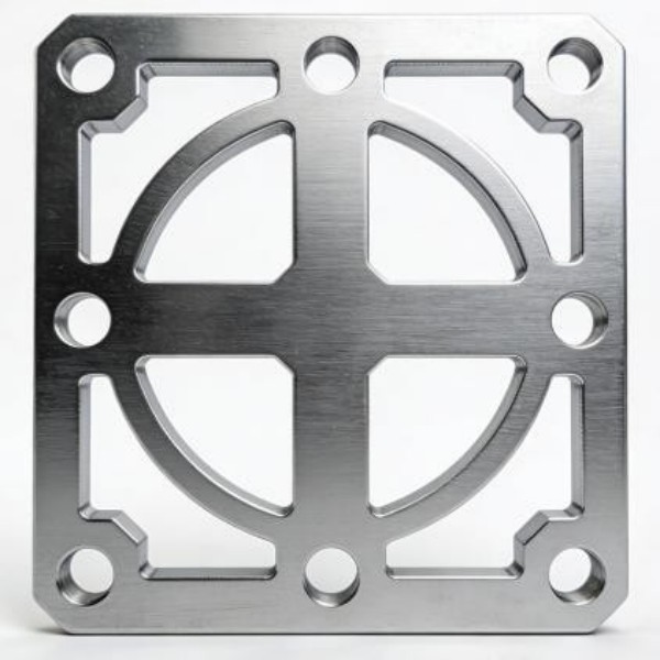
Rotating milling cutters do not create a perfectly sharp internal corner. The cutter radius remains in the pocket. If the mating part needs clearance, enlarge the internal radius, add an intentional relief or change the mating geometry. Do not force a sharp corner when only clearance is needed.
Use the largest acceptable internal radius
A larger radius can permit a larger, more rigid tool. That usually gives the process planner more options. The exact radius should come from the mating geometry and part-specific review, not a copied ratio. Adjacent corner transitions also matter: inconsistent radii may cause extra tool changes without improving function.
Open deep pockets and narrow channels where function allows
As a pocket becomes deeper relative to its width, the cutter needs more reach. Long reach reduces rigidity, makes chip evacuation harder and can increase deflection or chatter. A narrow bottom corner may force the use of a small tool for the full depth even when most material could be removed with a larger cutter.
Useful alternatives include a wider pocket, a stepped cavity, a larger bottom radius, access from another side, a split assembly or a near-net blank. Each alternative changes strength, sealing and assembly, so it requires design approval.
Treat undercuts as named features
An undercut may need a lollipop cutter, T-slot cutter, keyseat cutter, broach, EDM process or another special route. Define its functional width, depth, corner condition and access. If the feature exists only because two CAD surfaces intersected, remove it. If it retains a seal or ring, keep the functional geometry and allow the supplier to review tool availability.

05 · RigidityControl thin walls, tall bosses and slender features
Thin geometry can move during cutting, clamping, heat treatment, coating and inspection. The risk is not determined by thickness alone. Material, unsupported span, wall height, cutter engagement, stock removal pattern, local ribs, clamp position and required tolerance all contribute.
| Feature | Manufacturing risk | Possible design response |
|---|---|---|
| Broad thin wall | Deflection under cutting or clamping; free-state movement after release | Increase thickness, shorten span, add support, relax noncritical form or leave temporary stock |
| Tall narrow boss | Vibration, bending and difficult finishing near the base | Increase base section, add a fillet, reduce height or create a supported geometry |
| Long slender shaft | Tool-force deflection, chatter and runout changes | Provide support access, review center features, change sequence or increase section |
| Thin sleeve | Chuck distortion and out-of-round condition after unclamping | Review jaw strategy, leave finishing allowance or change blank and sequence |
| Uneven material removal | Residual-stress release can change flatness or position | Balance geometry, rough and finish in stages, or review stress-relief needs |
If a thin wall is functionally required, state the free-state requirement and inspection method. The supplier may propose staged roughing, temporary supports, reduced cutting forces or custom workholding. Those measures can be appropriate, but they belong in the quote because they add process planning and cycle time.
Material condition matters too. Use the CNC machining materials guide to connect stiffness, condition, blank form and post-processing to the geometry rather than selecting an alloy independently.
06 · Repeated featuresDesign holes and threads with entry, depth and inspection in mind
Holes look simple in CAD because their axes and end conditions are exact. In production, a tool must enter from a reachable direction, evacuate chips and stop or break through without damaging another surface.
Define the hole that function needs
- State whether the hole is through, blind, flat-bottomed, counterbored, countersunk, reamed or threaded.
- Give drill-point clearance at the bottom of a blind drilled hole when the full cylindrical depth matters.
- Avoid deep small-diameter holes unless flow, weight or assembly requires them.
- Keep intersecting holes and cross passages inspectable and deburrable.
- Clarify whether breakthrough marks are permitted on internal surfaces.
- Use a position control and datum reference when assembly location matters more than coordinate limits.
Specify useful thread engagement, not a tapped depth by habit
Separate full thread depth from drilled-hole depth. Blind tapping needs chip and tool clearance beyond the usable threads. Identify the thread standard, size, class, handedness and any insert requirement. If the thread will be plated or anodized, state the final gaging condition and whether masking or compensation is required.
Tool access also applies to edge distance and wrench clearance. A thread that is easy to model close to a wall may be hard to tap, inspect or assemble. Where a fastener head or tool must enter, include that physical envelope in the design review.
07 · Product definitionTolerance the function, not the appearance of precision
ASME describes Y14.5 as the authoritative guideline for stating and interpreting GD&T requirements on drawings and digital models. Its purpose is to communicate form, fit, function and interchangeability. DFM uses that language to identify what must remain related through machining and inspection.
Start with the interfaces: bearing seats, locating holes, sealing faces, sliding diameters, mounting planes and patterns. Build the datum reference frame from the way the component locates in the assembly where practical. Then apply controls that express the functional relationship.
The CNC machining tolerances guide explains size, form, orientation and location in more detail. The short DFM rules are:
- Use individual tight limits only where the function or interchangeability requires them.
- State a documented general tolerance for unmarked, noncritical dimensions.
- Avoid redundant dimension chains that conflict or obscure the controlling requirement.
- Keep critical features related to a coherent datum structure.
- Confirm that every tolerance has an accessible, suitable inspection method.
- State whether requirements apply before or after heat treatment, grinding, coating or assembly.
Surface requirements deserve the same discipline. ASME B46.1 distinguishes roughness, waviness and lay; a fine Ra value alone does not define a full functional surface. Use the surface finish guide to specify texture, treatment, masking and final inspection without covering every face in an expensive blanket requirement.
08 · Full processPlan the blank, heat treatment and finish together
A DFM review should not stop at the toolpath. Stock size, material condition and the amount removed from each side influence workholding, material yield and stability. For production volume, compare billet machining with casting, forging, extrusion or tube when those routes match the application.
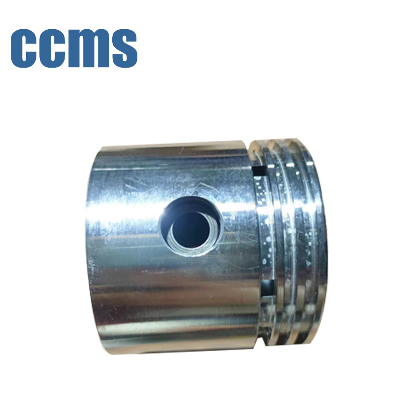
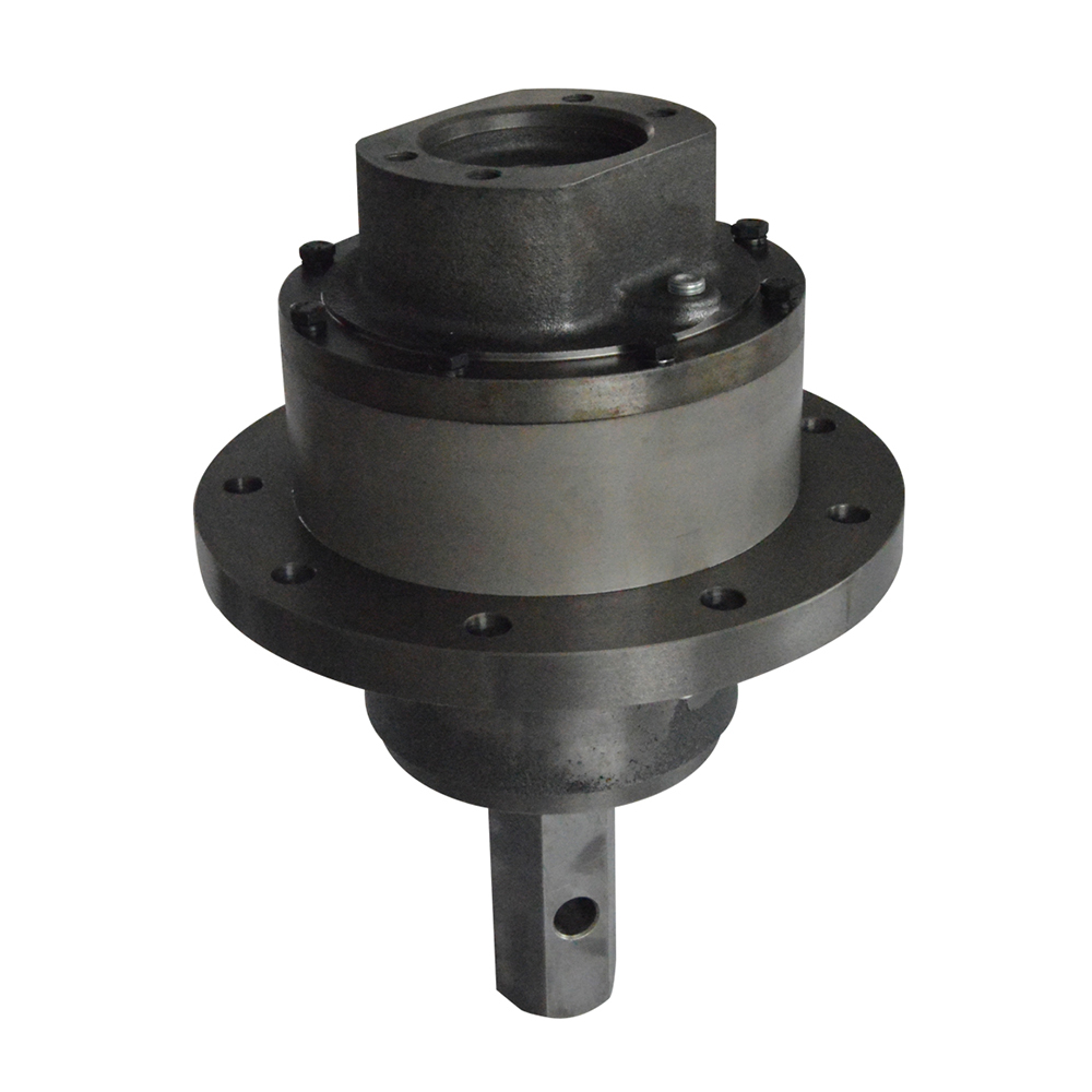
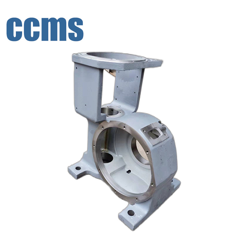
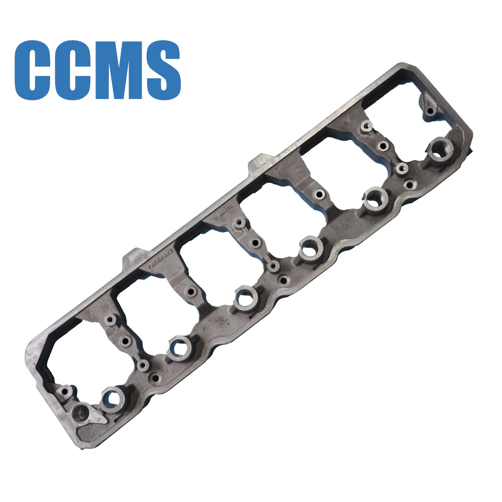
The geometry pictured below comes from a CCMS page for CNC-turned components. Treat it as product context, not a promise that the same material, tolerance or process applies to a new drawing. A part-specific route still depends on the blank, feature relationships and inspection scope.

Ask four sequence questions
Quantity changes the best answer. Standard stock and general-purpose workholding may suit prototypes that will change. A stable repeat order may justify a near-net blank, dedicated fixture or combined process. Give suppliers prototype quantity, batch quantity and expected annual demand so the quotation compares realistic routes.
09 · Release gateRun a feature-by-feature DFM review
Use the following review before requesting a firm production quote. The designer owns functional changes; the supplier owns the proposed process assumptions. Record both.
CNC machining design checklist
- Confirm the controlled 3D model, 2D drawing, part number and revision.
- Mark functional interfaces, critical characteristics and mating-part context.
- Identify the dominant geometry and likely turning, milling or combined route.
- Review raw-stock or near-net blank options against quantity and design maturity.
- Map locating, clamping and tool access for each required orientation.
- Increase internal radii and open deep or narrow features where function allows.
- Review thin walls, tall bosses, slender shafts and uneven stock removal.
- Define holes, drill-point clearance, threads, undercuts and deburring access.
- Apply individual tolerances and fine texture only to functional surfaces.
- Define heat treatment, finish, masking and the final dimensional condition.
- Match critical features to practical measurement methods and reports.
- Document approved alternatives instead of allowing undefined equivalents.
Send the same package to every bidder. The CNC machining RFQ checklist covers materials, quantities, documents, delivery and commercial scope, while the inspection guide helps define first article, sampling, reports and traceability.
| Red flag | Ask before release | Possible action |
|---|---|---|
| Access Sharp internal corner at full pocket depth | Does the mating part actually require a sharp corner? | Add radius, corner relief or another approved process |
| Rigidity Tight form tolerance on a broad thin wall | In what state and setup is the wall functional? | Support, thicken, change sequence or define free-state inspection |
| Setup Critical features on many faces with unrelated datums | Which interfaces establish assembly location? | Consolidate the datum structure and review orientation transfers |
| Tooling Deep small hole with no exit or chip path | Is the diameter and depth fixed by flow or assembly? | Increase size, reduce depth, allow alternate access or use a special process |
| Finish Coating covers threads, fits and electrical contacts | Which surfaces need protection and which must remain bare? | Add a masking map and state final acceptance dimensions |
| Definition Model and drawing disagree | Which file governs and what is the current revision? | Correct the package before suppliers quote |
10 · Designer questionsFrequently asked questions
What makes a part easy to CNC machine?
A machinable design gives the workpiece stable locating and clamping surfaces, allows rigid tools to reach every feature, avoids unnecessary setup changes and applies tight tolerances or fine finishes only where function requires them.
Why do internal corners need a radius in CNC milling?
Rotating milling cutters create radiused internal corners. A larger permissible radius can allow a larger and more rigid tool, while a sharp internal corner may require another process or a specific relief feature.
Should every CNC machined dimension use a tight tolerance?
No. Apply individual tight tolerances to functional features and relationships. Use a documented general tolerance for noncritical dimensions, and make sure every requirement can be measured in the stated final condition.
What should I send for a CNC machining DFM review?
Send the controlled 3D model and 2D drawing, material and condition, quantities, critical features and datums, surface and treatment requirements, inspection documents, mating-part context where useful and the target production stage.
Review manufacturability before the production quote.
Send the controlled model and drawing, material, quantities, critical features and finishing requirements for a part-specific review.
Request a DFM reviewView CNC machining parts