
Turning is usually the direct route for geometry built around one centerline. Milling is usually the better fit for faces, pockets, slots and features arranged across several planes. Parts that need both should be planned as a combined process, with the datum strategy decided before quotation.
Choose CNC turning when the part's functional geometry is mainly concentric with a rotational axis. Choose CNC milling when the part is prismatic or requires controlled features on several faces. Choose a combined route when a turned body also needs milled flats, cross holes, keyways or off-axis pockets. The lowest-risk process is the one that creates the critical relationships with the fewest datum transfers, not simply the machine with the shortest cycle time.
CNC milling and turning are both subtractive machining processes, but they establish geometry in different ways. That difference affects tool access, workholding, concentricity, setup count, inspection and cost. A drawing may be physically possible on either machine while still having one clearly better production route.
Process selection should therefore start before a buyer asks for a unit price. Mark the functional interfaces, identify which features share a datum, and separate round geometry from prismatic geometry. Then the supplier can decide whether to turn, mill, transfer between machines or use live-tooling equipment.
01 · FundamentalsThe basic difference between CNC milling and turning
In CNC turning, the main spindle holds and rotates the workpiece while tools remove material. In CNC milling, the spindle rotates the cutting tool while the workpiece is held on the machine table. Autodesk's official machine kinematics documentation uses this same distinction when it describes lathes, mills and combined machines.
| Decision factor | CNC turning | CNC milling |
|---|---|---|
| Primary motion | The workpiece rotates | The cutting tool rotates |
| Natural geometry | Cylinders, cones, shoulders, grooves and concentric bores | Faces, pockets, slots, contours and features on several planes |
| Typical stock | Bar, tube, forgings or round cast blanks | Plate, block, extrusion, casting or forging |
| Datum strength | Strong control of features related to the spindle axis | Strong control of features related to located faces and work offsets |
| Common secondary need | Live-tool milling for flats, cross holes and keyways | Rotary-axis work for cylindrical or multi-face access |
| Main planning risk | Irregular features can require extra tools or another machine | Round features can need indexing, circular interpolation or a turned operation |
These are process tendencies, not rigid boundaries. A mill can produce a circular pocket or bore. A turning center with live tooling can drill or mill features while the part remains in the spindle. The engineering question is which route creates the required geometry and relationships with acceptable stability.
02 · Shape firstChoose the process from the part's dominant geometry
A useful first pass is to imagine the part with every small hole, thread and chamfer removed. If the remaining body is a shaft, sleeve, piston, bushing or flange built around one axis, turning deserves the first review. If the remaining body is a plate, bracket, manifold, housing or block, milling is usually the better starting point.
The centerline controls the OD, bore, shoulders, grooves, tapers or threads.
Located faces control pockets, hole patterns, slots, sealing surfaces or profiles.
A concentric body also carries functional features that do not share the turning axis.
Do not let the largest visual feature decide by itself. A rectangular housing may contain a precision bore that controls assembly. A round flange may have a bolt pattern and mounting face that dominate inspection. The controlling datum and the most difficult relationship may matter more than the overall silhouette.
03 · Feature mapUse a feature matrix instead of a one-line rule
| Part feature | Likely first choice | What to confirm |
|---|---|---|
| Concentric outside and inside diameters | Turning | Chuck access, wall stability, runout and inspection datum |
| Face groove or external groove | Turning | Tool reach, groove width, corner radii and chip control |
| Flat sealing face with a port pattern | Milling | Flatness, surface texture, hole location and one-setup access |
| Deep pocket in a block | Milling | Tool reach, internal radii, wall deflection and chip evacuation |
| Shaft with cross hole and wrench flats | Turning plus milling | Angular orientation, datum transfer and whether live tooling is suitable |
| Round flange with bolt circle | Combined or indexed milling | Bore-to-pattern position, face relationship and fixture strategy |
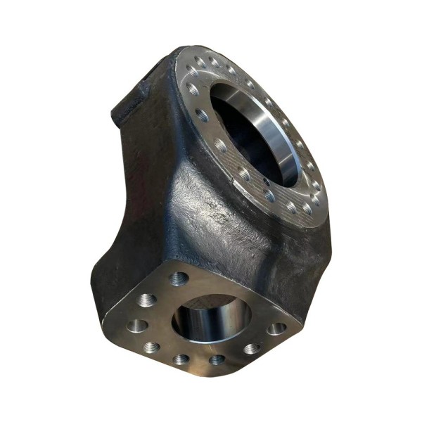
| Cast housing with machined bores and pads | Milling, boring or combined operations | Blank variation, locating pads, machining allowance and datum sequence |
The matrix tells a supplier what must stay related. It does not prescribe a brand or model of machine. That choice depends on size, travel, spindle configuration, tooling, production quantity and the equipment available at the selected shop.
04 · RelationshipsLet tolerances and datums shape the setup plan
Turning naturally keeps features related to the spindle axis in one setup. That can help when an outside diameter, shoulder and bore must remain concentric. Milling naturally keeps faces and hole patterns related to a located work coordinate system. Trouble begins when a critical requirement crosses from one setup or machine to another without a stable datum-transfer method.
Before selecting the process, mark which relationships affect fit, sealing, motion or interchangeability. Then ask whether the supplier can create and inspect those features from a common datum. The companion CNC machining tolerances guide explains why blanket tight tolerances are less useful than controls tied to function.
Check these relationships before approving the route
- Runout or concentricity between turned diameters and bores
- Perpendicularity between a mounting face and a rotational axis
- Position of cross holes, ports or bolt circles relative to the centerline
- Distance and orientation between features machined from opposite sides
- Dimensions that apply after heat treatment, grinding or coating
05 · Production contextMaterial, blank shape and quantity can change the answer
Geometry leads the decision, but the starting material and batch plan can change the economics. A round part cut from bar may suit turning. A repeat housing may begin as a casting or forging with separate machining allowance on bores, faces and holes. A prototype might be milled from billet even when a near-net blank is planned for production.
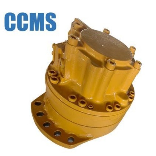
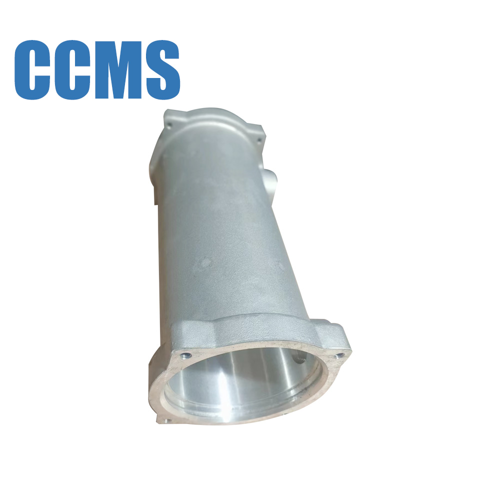
CCMS states that its CNC machining parts scope includes cast iron, gray iron, stainless steel and cast aluminum, plus turning, milling, drilling and tapping. Those are company-published capabilities. They do not establish the best route for a particular drawing. The controlled model, material condition, blank allowance and quantity still need review.
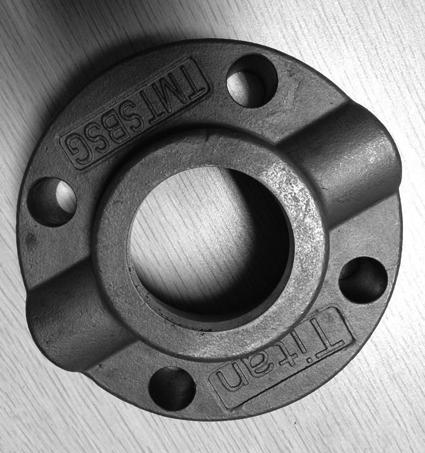
For this type of part, buyers can compare a two-machine route with a suitable combined process. The quotation should state blank type, setups, one-time tooling, inspection scope and any process assumptions. The CNC machining cost guide provides a broader framework for reviewing those cost drivers without weakening the part's function.
06 · Milling-led partsChoose CNC milling when faces and feature locations control the part
Milling is the natural choice for prismatic work: plates, brackets, housings, manifolds, fixtures and cast components with machined pads. The workpiece is located against known surfaces while rotating tools approach from one or more directions. Three-axis work may cover a simple part. Indexed fourth-axis or multi-axis equipment can reduce reclamping when features sit around the component.
Milling is usually a strong fit when the drawing has:
- Several flat faces with controlled relationships
- Pockets, steps, slots, channels or nonround profiles
- Hole patterns distributed across one or more faces
- Contoured surfaces that require coordinated tool motion
- A cast or forged housing with machined pads and bores
Its limits usually appear in tool reach, workholding, number of orientations and the rigidity of long or small cutters. Deep narrow pockets, inaccessible corners and thin walls need a part-specific review. Do not assume that adding more machine axes automatically lowers cost. Programming, access and fixturing still matter.
07 · Turning-led partsChoose CNC turning when the centerline controls the part
Turning is efficient for shafts, sleeves, bushings, rings, pistons, pins and other components whose functional surfaces share a rotational axis. The process can create outside diameters, faces, bores, shoulders, tapers, grooves and many thread forms while the workpiece remains located in the spindle.
Round does not automatically mean simple. A thin sleeve can distort under clamping. A long shaft may need support. A deep bore can limit tool reach and chip evacuation. Interrupted cuts on a casting or forging may also change tooling and process stability.
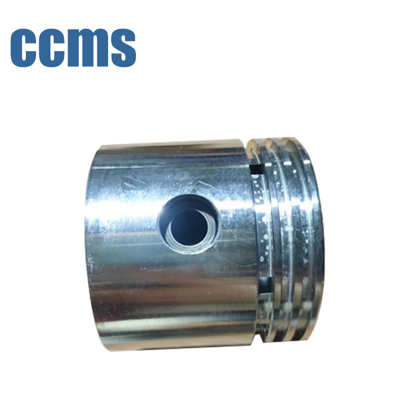
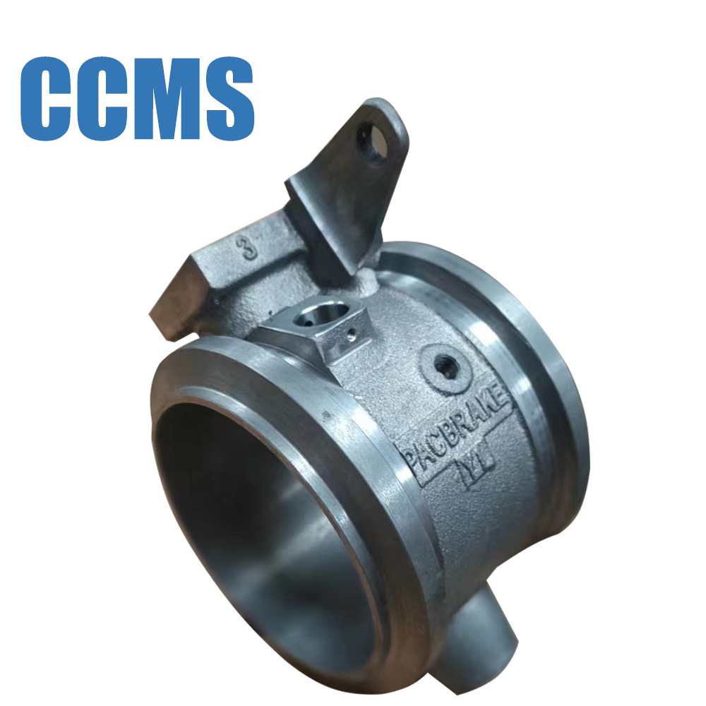
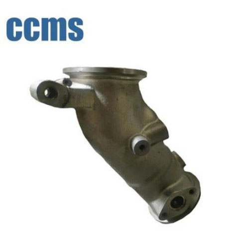
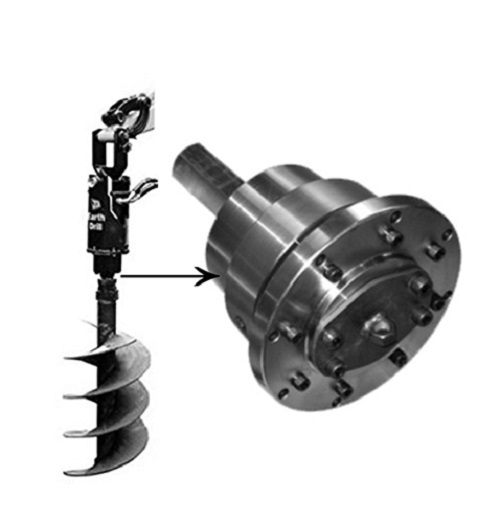
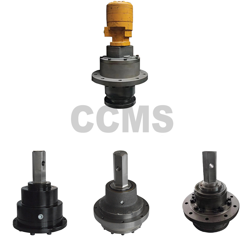
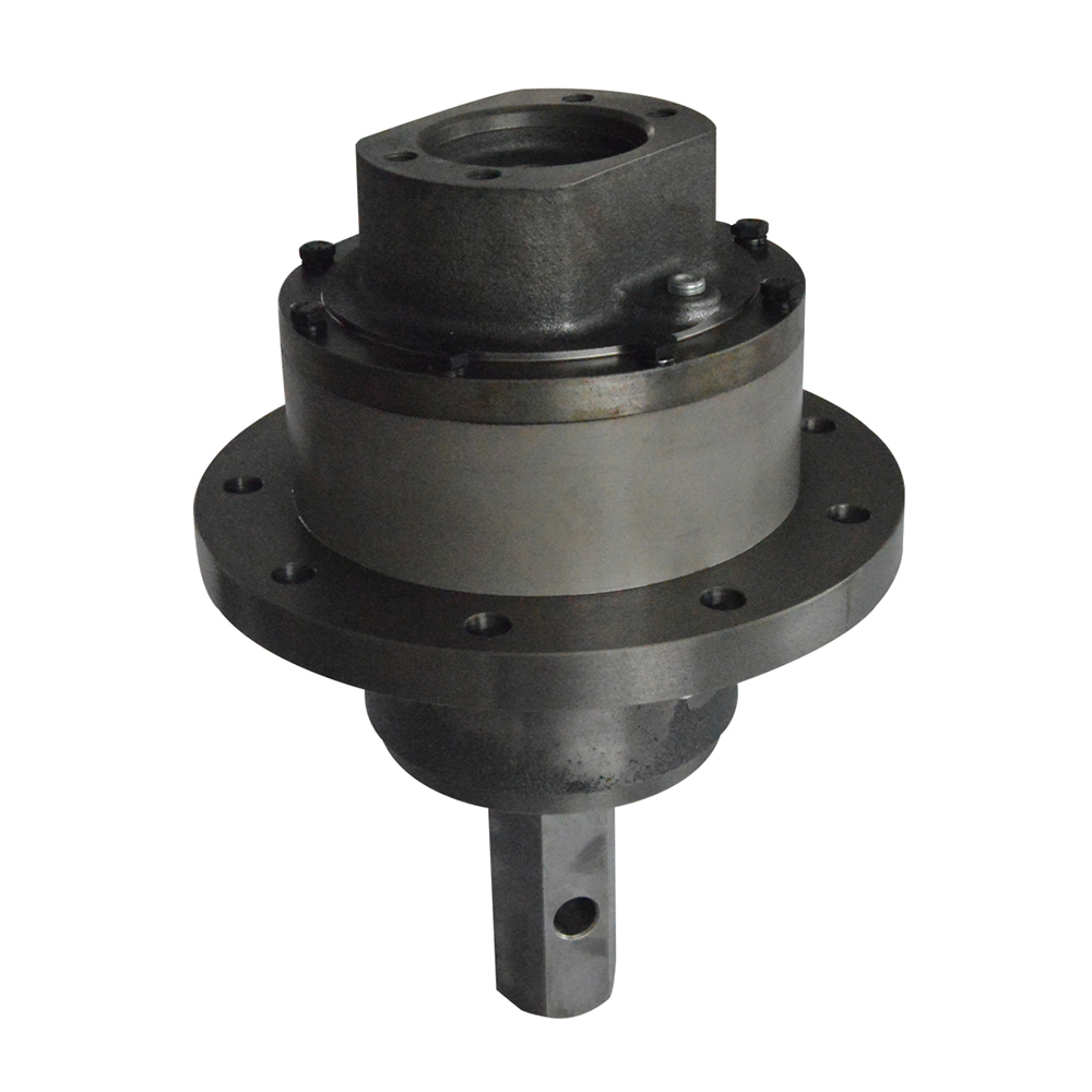
CCMS also publishes a dedicated example for cast iron parts using CNC turning and milling. Treat the listed product as capability context, not as proof that the same route or tolerance applies to a new component.
08 · Mixed geometryWhen to use both milling and turning
A part with a turned body and off-axis features may follow one of three routes: turn then transfer to a mill, mill then transfer to a lathe, or use a machine that supports both operation types. Autodesk describes turn-mill machines as lathes with live tooling and mill-turn machines as mills with turning capability. Its mill-turn overview notes that combining operations can reduce setup time and part handling.
Fewer transfers can protect relationships, but a combined machine is not automatically the cheapest option. Machine rate, programming, tooling, available capacity, workholding and batch size all influence the quotation. A stable two-machine route can be entirely appropriate when the datums are accessible and the transfer method is controlled.
| Route | Potential benefit | Question to ask |
|---|---|---|
| Turn, then mill | Creates a stable round datum before off-axis features | How will the second setup locate and orient from the turned geometry? |
| Mill, then turn | Creates gripping or locating features before spindle work | Can the lathe hold the milled shape without distortion or loss of orientation? |
| Turn-mill or mill-turn | May keep critical features in one machine cycle | Does the available configuration reach every feature and support inspection needs? |
09 · QuotationWhat to send so the supplier can choose the process
A supplier cannot make a defensible milling-versus-turning decision from a screenshot and quantity alone. Send the controlled model and drawing, then identify the requirements that cannot move. The existing CNC machining RFQ checklist covers the full quotation package.
Process-selection package
- Matching 2D drawing and 3D model with revision status
- Material grade, stock form, condition and approved alternatives
- Critical datums, fits, runout, position and surface requirements
- Features that must stay related in one setup or inspection frame
- Prototype quantity, production batch and estimated annual demand
- Heat treatment, coating, grinding and other secondary operations
- Required inspection records, sampling and acceptance stage
- Delivery destination, target date and packaging constraints
Ask the supplier to state the proposed route, setup assumptions, blank type and inspection plan. If two suppliers quote different methods, compare the scope before comparing unit prices. The CNC supplier audit guide provides questions for checking whether the proposed equipment and controls fit the drawing.
CCMS's published machining services list milling, turning, drilling, tapping and precision grinding from prototype through production. For a specific part, use the drawing review rather than assuming capability from a category page.
10 · Buyer questionsFrequently asked questions
Can a CNC mill make round parts?
Yes. A mill can produce bores, circular pockets and external circular profiles. A rotary axis can also index or rotate a part. Turning is often the more direct route when most functional geometry shares one centerline, but the correct choice depends on size, features, quantity and available equipment.
Can a CNC lathe mill flats and drill cross holes?
A turning center with live tooling and suitable axes may mill flats, drill cross holes and create other off-axis features. The supplier must still confirm tool access, angular orientation, workholding and whether every feature can be completed in the proposed setup.
Is CNC turning always cheaper than milling for round parts?
No universal price rule applies. Turning can remove material efficiently from rotational parts, but cost also includes stock, setup, tooling, secondary features, inspection and quantity. A round part with extensive off-axis work may need a combined route.
Does mill-turn machining always improve accuracy?
Reducing reclamping can help preserve relationships between features, but the machine configuration, process plan, tooling, thermal conditions and inspection method still matter. Accuracy should be assessed against the actual drawing rather than the process name.
Should the drawing specify milling or turning?
Specify a process only when design authority, qualification or another controlled requirement makes it mandatory. Otherwise define the functional geometry, material, datums, tolerances, finishes and inspection needs, then allow qualified suppliers to propose a route for approval.
Technical references and scope
- Autodesk Fusion: Machine kinematics, used for the distinction between mills, lathes, turn-mill and mill-turn configurations.
- Autodesk: CNC milling, used for the official overview of milling, turning and axis configurations.
- Autodesk: Mill-turn software, used for the combined-process description.
- CCMS CNC machining parts and CCMS services, used only for company-published capability and material scope.
Send the part before the setup plan is fixed.
Include the 2D drawing, 3D model, material, quantities, finishes and critical inspection needs. CCMS can review whether the inquiry fits its turning, milling or combined machining scope.
Request a drawing review View a milling and turning example