
A tighter number is not automatically a better specification. The right tolerance protects fit and function while remaining practical to manufacture and verify.
CNC machining tolerances define the permitted variation in a part’s size, form, orientation and location. There is no single “standard tolerance” that suits every machined feature. Use a documented general tolerance for noncritical dimensions, then apply individual dimensional or geometric controls only where assembly, sealing, alignment, motion or interchangeability requires them.
A tolerance is a functional and commercial decision, not a decoration on a drawing. It tells manufacturing how much variation is acceptable and tells inspection how acceptance will be judged. When the requirement is incomplete or unnecessarily restrictive, the result can be clarification delays, avoidable process steps or quotations that are difficult to compare.
This guide is written for mechanical designers, sourcing teams and quality personnel preparing drawings for custom CNC machining. It explains the decisions behind tolerance selection; it does not replace the drawing standard, fit analysis or engineering validation required for a specific product.

Those controls answer different questions. A bore may be within its size limits yet be misplaced relative to its mounting face. A shaft diameter may be acceptable while the surface has too much runout relative to a bearing datum. Checking size alone does not prove every functional relationship.
How large or small may a diameter, width, thickness or other feature of size be?
How much may a surface or feature depart from straightness, flatness, circularity or cylindricity?
How must a feature relate to functional datums or other features?
What small-scale surface condition is required for sealing, friction, wear or appearance?
Accuracy, precision and tolerance are not interchangeable
Tolerance is the permitted variation in the specification. Accuracy describes closeness to a reference value, while precision commonly describes repeatability. A supplier’s process capability must be evaluated against the specific feature, setup, material and inspection method—not inferred from a single marketing number.
Choose the control that matches the design risk
| Control | Best used for | Typical design question | Inspection consideration |
|---|---|---|---|
| Limit dimensions | Direct upper and lower size boundaries | What sizes are acceptable? | May be checked with suitable variable or attribute gaging |
| Plus/minus tolerance | Linear, angular or size variation | How far may the value vary from nominal? | Method depends on feature and required uncertainty |
| Fit designation | Mating shafts and holes | Is clearance, transition or interference required? | Both mating feature limits matter |
| Geometric tolerance | Form, orientation, location, profile or runout | How must the feature relate to a datum framework? | Datum simulation and measurement strategy must agree with the drawing |
| Surface texture | Sealing, sliding, bearing, fatigue or cosmetic surfaces | What surface condition supports function? | State parameter, units, direction and evaluation requirement where relevant |
A coordinate tolerance can appear simple but may not express the real boundary needed by the assembly. Conversely, a complex GD&T callout is not useful merely because it looks more technical. The specification should describe the functional requirement in a way production and inspection can interpret consistently.
What does “standard CNC machining tolerance” mean?
There is no universal standard value for all CNC-turned and CNC-milled parts. Machine type, feature size, material, geometry, tool access, wall thickness, thermal conditions, production volume and measurement method all affect what is practical.
In procurement, “standard tolerance” usually refers to one of three things:
- A company’s documented title-block tolerances for dimensions without individual limits.
- A tolerance class from a named national or international standard.
- A supplier’s default commercial capability for a defined process and part condition.
These are not automatically equivalent. Write the governing system, edition and class on the drawing. The ISO page for ISO 2768 describes general tolerances for linear and angular sizes, while its current listing shows a new edition under publication in 2026. ISO also identifies ISO 22081:2021 as the available standard for general geometrical specifications after ISO 2768-2:1989 was withdrawn. Confirm the document status and edition used by your organization before revising a drawing.
Do not write “standard tolerance applies” without naming it
The supplier cannot know whether “standard” means your title block, an ISO class, an ASME-based drawing practice or an internal shop default. Ambiguity at quotation becomes disagreement at inspection.
Use GD&T to communicate function—not to decorate the drawing
ASME Y14.5-2018 (R2024) establishes symbols, rules, definitions and practices for dimensioning and geometric tolerancing. ASME describes GD&T as a design language for communicating form, fit, function and interchangeability on drawings and digital product definitions.
The datum reference frame should represent how the part locates or functions in the assembly. A convenient machining surface is not necessarily the correct functional datum. Before applying position, profile, orientation or runout, ask how the actual part will contact its mating components and how inspection will establish those relationships.
A bolt-hole pattern relative to a mounting face
Suppose a cover is located by its mounting face and two locating features. The design question is not only whether each hole’s X and Y coordinates are individually close to nominal. It is whether the pattern assembles correctly relative to the functional interfaces.
- Establish datums from the interfaces that locate the part.
- Control the hole pattern relative to those datums under the selected drawing standard.
- Verify that datum targets, modifiers and acceptance boundaries reflect the assembly analysis.
- Confirm that the planned measurement method can establish the specified datum reference frame.
This is an explanatory example, not a complete feature control frame. The actual callout must come from the product’s tolerance analysis.
How tight tolerances affect CNC machining cost
Tighter tolerances do not add a fixed percentage to part price. They change the manufacturing plan. A requirement that is routine on one feature can be difficult on another because tool access, feature depth, datum transfer, distortion or inspection access differ.
| Cost driver | Why tolerance matters | Useful design response |
|---|---|---|
| Additional setups | A relationship across setups may accumulate locating error | Keep related critical features in a common datum strategy where practical |
| Finishing operations | Grinding, honing, lapping or other processes may be required after machining | Specify the functional need and affected surface only |
| Tool reach and rigidity | Deep bores, slender tools and interrupted cuts can reduce stability | Review depth, corner, wall and access constraints |
| Temperature and distortion | Material removal, heat treatment and environment can alter geometry | Define the final condition and inspection stage |
| Inspection effort | Complex datum structures or inaccessible features require more planning | Agree on acceptance method for critical features before production |
| Scrap and rework exposure | A small process shift can make a tightly controlled feature unacceptable | Use tight limits only where justified by functional analysis |
The most useful cost-reduction question is not “How loose can every dimension be?” It is “Which requirements protect function, and which ones are tighter than the product needs?” Mark critical characteristics clearly, leave noncritical features under a sensible general tolerance and invite manufacturability feedback before design release.
If you are already preparing an inquiry, use the companion CNC machining RFQ checklist to send matching drawing revisions, quantities, material, finishes and inspection requirements.
Material and geometry can change what is practical
A tolerance cannot be evaluated separately from the workpiece. Material stability, residual stress, hardness, thermal expansion and machinability interact with part geometry and process sequence. Thin walls may deflect under cutting or clamping. Long slender features may bend. Large differences in removed stock can release stress and change shape after unclamping.
Review clamping force, tool pressure, wall uniformity and the free-state inspection condition.
Tool reach, chip evacuation and access can matter more than the nominal size alone.
Datum selection, stock allowance and variation in the incoming blank affect machining strategy.
Sequence, hardness, distortion allowance and the final inspection condition must be defined.
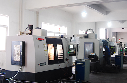
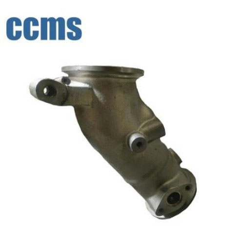
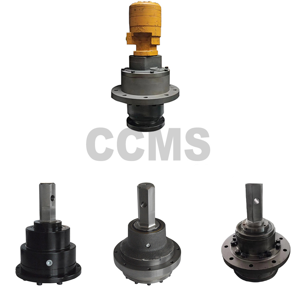
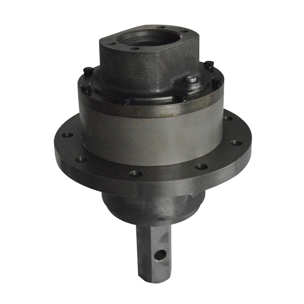
CCMS publicly lists CNC machining of cast iron, aluminum alloy, gray iron and stainless steel, including custom parts made from drawings. That range does not mean every tolerance is available on every geometry or material. The correct next step is a part-specific review through the CCMS CNC machining parts service.
Account for surface finish, heat treatment and coating
Dimensional acceptance must refer to a defined condition. Coating adds material. Heat treatment can change size or geometry. Deburring and polishing can affect edges and surfaces. If the drawing does not say when dimensions apply, the machine shop and buyer may inspect different conditions.
- State whether dimensions and geometric tolerances apply before or after finishing.
- Identify masked surfaces and threaded features.
- Name the process specification, class, thickness or hardness requirement where applicable.
- Separate surface-texture requirements from dimensional limits.
- Define whether coating buildup must be included in mating-feature limits.
- Establish the acceptance condition after stress relief or heat treatment.
Do not use one roughness value on every surface by default
A sealing face, bearing seat and nonfunctional exterior surface do different jobs. Apply surface requirements where function or appearance needs them, and identify the parameter and units under the selected surface-texture standard.
Plan measurement while specifying the tolerance
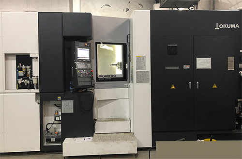
A tolerance that cannot be measured consistently is not a complete acceptance requirement. The method should suit the feature, tolerance, surface, datum scheme, quantity and required confidence. Calipers, micrometers, bore gages, height gages, surface instruments, functional gages and coordinate measuring machines do different jobs; no single instrument is best for every characteristic.
NIST’s work on dimensional measurement services explains the role of traceability to the SI unit of length. NIST has also published detailed work on measurement uncertainty for coordinate measuring machines. For purchasing purposes, the practical lesson is that the measurement result, method, setup, environment and uncertainty all matter when the tolerance approaches the limits of the inspection process.
| Drawing requirement | Inspection question to resolve |
|---|---|
| Tight bore or shaft size | Which instrument, contact condition and temperature basis are appropriate? |
| Position or profile | How will datums be simulated and the result reported? |
| Runout | What establishes the datum axis, and is the surface accessible? |
| Surface roughness | Which parameter, cutoff, direction and location apply? |
| Free-state or flexible part | What restraint and inspection condition represent acceptance? |
| Coated feature | Is inspection required before coating, after coating or at both stages? |
CNC tolerance drawing checklist
Before releasing a drawing or requesting a quote, review it with manufacturing and inspection in mind:
- Identify the governing drawing standard, edition, units and projection method.
- Use one controlled revision across the 2D drawing and 3D model.
- Define a general tolerance for genuinely noncritical dimensions.
- Apply individual limits only where fit, function or risk justifies them.
- Choose datums from stable, accessible functional interfaces.
- Avoid duplicate or conflicting dimensions and controls.
- Fully specify holes, threads, edge conditions and surface texture.
- State material grade, form, condition and heat treatment.
- Clarify whether requirements apply before or after coating and finishing.
- Confirm that critical characteristics have a realistic inspection plan.
- Share prototype, batch and annual quantities with the supplier.
- Request manufacturability feedback before freezing high-cost requirements.
How this guide was prepared
This article synthesizes current public information from ASME, ISO and NIST with the publicly described CNC machining and inspection scope on CCMS product pages. It does not claim a universal CCMS tolerance or replace part-specific engineering review. A named standard, controlled drawing and agreed inspection plan remain the governing sources for production acceptance.
Frequently asked questions
What is a standard CNC machining tolerance?
There is no single universal tolerance that fits every CNC process, material, feature size and part geometry. A drawing should identify the governing standard or company title-block tolerance and individually control features whose function requires a different limit.
Do tighter CNC machining tolerances increase cost?
They can. A tighter requirement may demand additional setups, slower finishing passes, more capable equipment, temperature control, greater inspection effort or higher scrap risk. The effect depends on the feature and process, so suppliers should review the complete drawing.
When should GD&T be used on a machined part?
GD&T is useful when form, orientation, location, runout or profile must be controlled relative to functional datums. It communicates design intent more clearly than unrelated coordinate tolerances when correctly applied under a named standard.
How should coating be handled in a machining tolerance?
State whether dimensions apply before or after coating, define masked areas and identify the coating specification and thickness where relevant. The manufacturer needs this information to plan machining allowance and final inspection.
Standards and technical references
Technical references are linked beside the claims they support: ASME Y14.5-2018 (R2024), ISO 2768 status information, ISO 22081:2021 and NIST dimensional-metrology resources. Always use the licensed standard and revision required by your contract; this article is an explanatory buyer’s guide.
Do your tolerances match the part’s function and manufacturing plan?
Send the current drawing, 3D model, material, quantities and inspection requirements. CCMS can review whether the inquiry contains enough information for its custom CNC machining scope and raise technical questions before quotation.