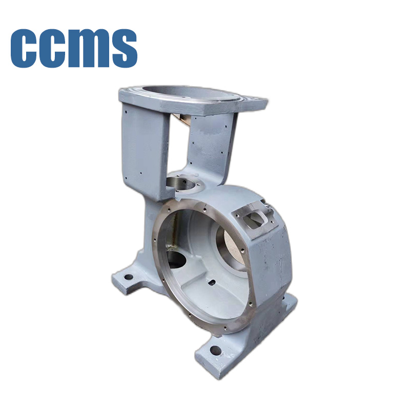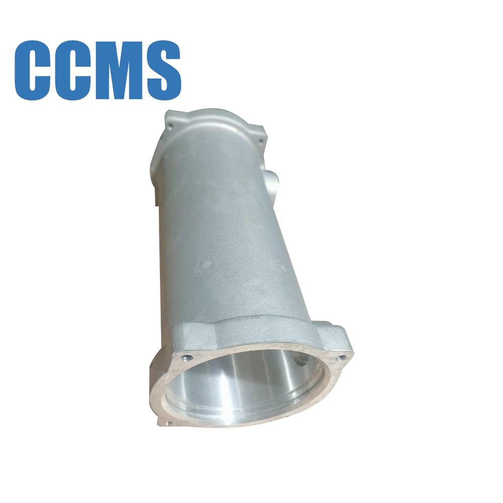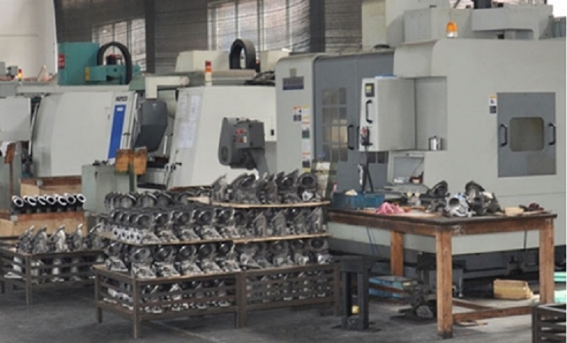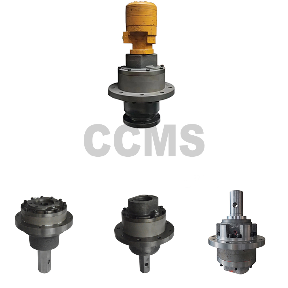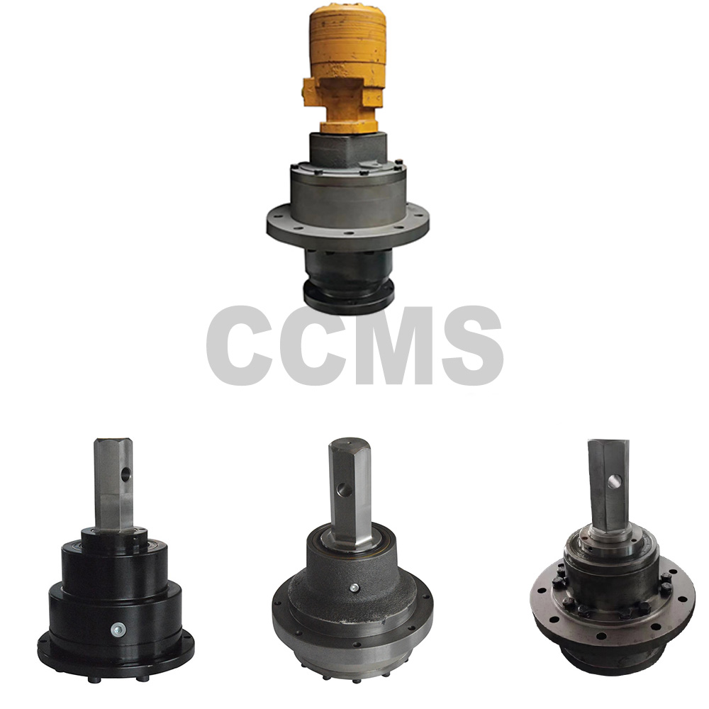

A casting can meet its blank dimensions and still fail to clean up during machining. The missing check is often the position of the available metal relative to the finished part. This guide explains how to check that relationship and what to do when a cut exposes a questionable surface.
What makes a casting ready for CNC machining?
A usable casting needs enough local machining stock, a repeatable way to locate and support it, and agreed acceptance criteria for the material and finished surfaces. Check those conditions against the finished drawing before processing a batch. Overall blank size alone cannot prove that every bore, sealing face or wall will meet the final requirements.
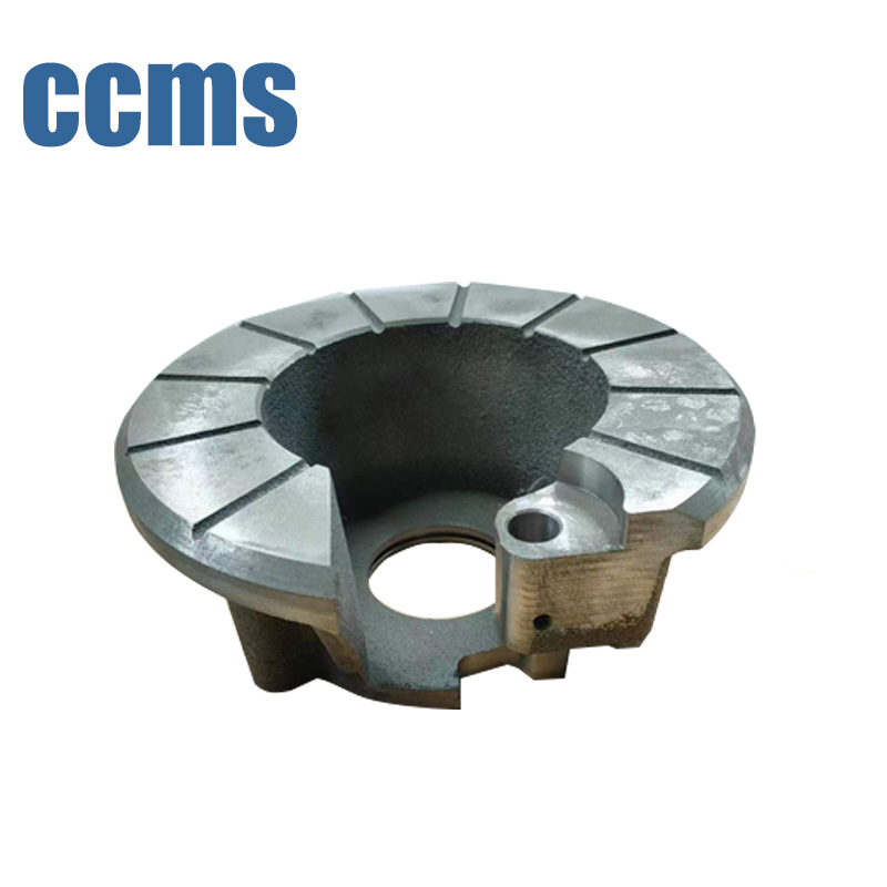
CNC machining castings means removing material from a cast blank to produce specified finished features. Much of the original shape may remain as cast, while selected faces, bores and threads receive tighter dimensional or surface requirements.
The casting-to-machining route applies to products such as gravity cast aluminum CNC machining parts and cast iron components. For each part, the blank definition and machining plan must work together to produce the required finished geometry.

01 · Product definitionSeparate the casting requirements from the finished requirements
Before reviewing a quotation or sample, identify what the foundry must deliver and what the machine shop must produce. You can express these requirements on separate drawings or clearly distinguished views in a combined drawing. The requirement sets need to remain identifiable.
The published contents of ASME Y14.8-2022 (PDF) identify separate and combined drawing methods, as-cast surfaces, draft, wall thickness and datum referencing. Use the drawing standard specified by your project; this guide does not replace its detailed rules.
| Requirement set | What it needs to define | A useful review question |
|---|---|---|
| Cast blank | Material grade and condition, casting geometry, draft, allowable variation, machining stock and relevant acceptance criteria | Can this blank produce the finished part in the intended location? |
| Finished part | Final dimensions, GD&T, datums, surface texture, threads, remaining wall and functional tests | Can the finished component assemble and perform as specified? |
| Manufacturing plan | Initial locating points, supports, setup sequence, inspection stages and treatment sequence where applicable | How will the supplier preserve the required relationships through each operation? |
A note such as "machine all indicated surfaces" leaves a gap if no one defines how those surfaces sit within the raw casting. Ask for a drawing or model overlay showing the finished geometry inside the blank, aligned to the intended locating references.
02 · Available metalMachining allowance is different from casting tolerance
Machining allowance is the stock intended for removal. Casting tolerance is the permitted variation in the blank. A larger tolerance can consume stock on the side where you need it most, even when the casting passes its dimensional check.
ISO 8062-3:2023 addresses casting tolerances and machining allowance grades for indicated dimensions using ± tolerances. Its scope excludes undimensioned 3D CAD models. A reference to this standard therefore needs to suit the actual product definition; it does not by itself specify every finished machining requirement.
For an outside surface, the casting generally needs extra material outside the finished envelope. For a cast hole that will be bored larger, stock lies inside the finished bore boundary. In either case, evaluate the least-stock location, not an average.
- Align the blank to the proposed first-operation locating scheme.
- Compare the cast surfaces with the finished geometry along the full machining area.
- Include relevant size, form and positional variation, including possible core displacement.
- Check remaining walls and nearby cast passages at the same time.
- Agree a local cleanup requirement and a reserve for uncertainties with the responsible engineers.
There is no useful universal answer such as "leave 2 mm on every casting." The amount must suit the material, casting route, size, geometry, variation and required finished condition. Excess stock also means additional removal and may change which material layer becomes the finished surface.
For the finished feature, distinguish size from position and form. A bore can have the correct diameter while its axis is in the wrong place. The CNC machining tolerances guide explains these controls in more detail.
03 · Worked exampleWhy an undersize cast hole may still have too little stock
Consider a hypothetical circular cast hole that will be bored to a larger diameter. Assume the cast and finished axes are parallel. The cast hole is offset from the required finished axis after the blank is located in the proposed fixture.
| Input | Illustrative value | Meaning |
|---|---|---|
| Finished bore diameter, Df | 40.0 mm | Target used for this calculation |
| Largest cast-hole diameter, Dc | 37.6 mm | Largest circular opening considered |
| Axis offset, e | 0.7 mm | Displacement in the proposed setup |
| Additional radial reserve, u | 0.2 mm | Assumed budget for other uncertainties |
| Required local cleanup stock | 0.8 mm | Hypothetical project requirement, not a recommended industry value |
Check the side with the least stock
Minimum geometric radial stock = (Df − Dc) / 2 − e
= (40.0 − 37.6) / 2 − 0.7 = 0.5 mm
Stock after the assumed reserve = 0.5 − 0.2 = 0.3 mm
The result is below the assumed 0.8 mm cleanup requirement. This blank fails the example's stock check, even though the cast hole is smaller than the finished bore.
Ignoring offset gives 1.2 mm of nominal radial stock and the wrong conclusion. The calculation also shows why diameter alone is an incomplete incoming check.
This is a simplified geometric illustration, not a CCMS production result or a standard allowance calculation. Real cast holes can be tapered, irregular or tilted. Evaluate stock along their length and circumference. Where the finished bore has a size range, use the relevant limiting geometry for the worst-case review rather than automatically using its nominal diameter.
Repositioning the blank may redistribute stock, but only within the drawing's permitted relationships. Before changing location, check the opposite wall, neighboring holes, cast passages and final datums. A setup that saves one bore can make another feature impossible.
04 · Setup planningPlan how the first setup creates the later references
The final datum face may not exist when the raw casting reaches the machine. The first operation must locate the blank well enough to create usable machined references while preserving stock elsewhere.
Ask the supplier to distinguish product datums used to verify the finished drawing from manufacturing references used to hold the blank. They may coincide, but calling both "datum A" without showing their relationship can hide a setup error.
- Identify the initial contact areas or datum targets on the casting. Avoid leaving their selection to whichever rough patch happens to touch the fixture.
- Show which machined face, bore or locating feature the first operation establishes.
- Show how the next operation locates from those features and controls rotation.
- Verify finished features in the drawing's required datum reference frame.
Also review support and clamp positions. A repeatable location is not enough if the clamp distorts a thin section. Where deformation is a concern, include an inspection after release from the fixture under agreed measurement conditions.
When reviewing CNC turned and milled cast iron parts, ask how the turning and milling setups preserve the required relationships between features.
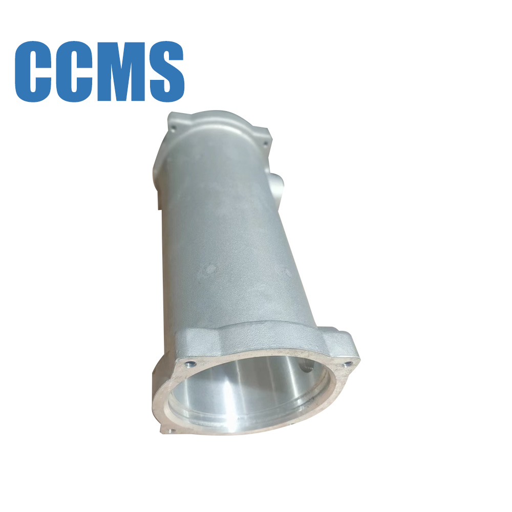
05 · Incoming inspectionInspect the blank before adding machining cost
Choose incoming checks around failures that would make subsequent work unusable. A large outside dimension is easy to measure, but a displaced passage or an undersize machining pad may matter more.
For steel castings, SFSA's ordering guidance recommends checking initial castings for sufficient stock on the surfaces to be machined. It also calls for machining surfaces and locating datums to be communicated to the foundry. The checklist below adapts that coordination principle into a review method; it does not transfer steel-specific dimensional limits to aluminum or cast iron.
| Check | What to establish | When to pause the route |
|---|---|---|
| Identity and revision | Blank number, tooling revision and traceability to the supplied records | The blank or records cannot be tied to the released definition |
| Material and condition | Specified grade, heat-treatment condition where required, and agreed evidence | Substitution, missing evidence or an unresolved condition mismatch |
| Local stock | Least-stock areas in the proposed setup, including hole and core position | Cleanup cannot be demonstrated at a required surface |
| Wall and passage geometry | Remaining wall after machining and relationships to retained cast features | A finished feature could breach a passage or violate a wall requirement |
| Locating and support areas | Contacts fit the intended fixture without interference or unstable seating | Flash, damage or surface variation prevents the intended location |
| Surface and internal acceptance | Specified visual checks and any required NDT, with defined coverage and limits | An indication needs evaluation, or a required examination is missing |
Record the measurement alignment with the results. A scan deviation map aligned by unrestricted best fit can look acceptable while concealing a problem in the actual machining location. Ask which surfaces or targets established the alignment and whether they represent the planned setup.
Sampling and examination coverage must come from the agreed inspection plan. An accepted sample does not automatically release every cavity, heat or lot. The CNC inspection and quality control guide covers how to connect results to specific characteristics and records.
06 · Feature prioritiesReview the features where small errors have larger consequences
Mark the functional areas on a sectioned drawing before discussing a general surface-quality requirement. The same visible discontinuity may require a different response on a cosmetic area, a seal track and a load-bearing section. Acceptance comes from the applicable requirements.
| Feature | What deserves an early check | What to define before machining |
|---|---|---|
| Sealing face or seal bore | Complete cleanup, surface discontinuities and the sealing path | Texture, geometry, surface acceptance and functional test where required |
| Bearing or locating bore | Stock around the full bore and its relationship to the final datums | Size, form, axis location and inspection alignment |
| Threaded boss | Material around the proposed hole and nearby cavities | Thread specification, engagement, wall requirement and examination scope |
| Thin wall beside a cast passage | Core displacement, local stock and clamp sensitivity | Minimum finished wall and a way to verify it |
| Retained as-cast area | Whether the finished location leaves the required envelope and clearance | Permitted surface condition, flash and local geometry |
A note such as "no porosity" needs an examination context: where to look, with what method, at which stage and to what acceptance threshold. An unqualified note can leave the purchaser and supplier judging different evidence.

07 · TroubleshootingWhat to do when machining exposes a hole or questionable area
Record the finding before anyone blends, fills or cuts it away. A photograph can document an opening's surface appearance and location, but it cannot establish its hidden extent or prove that it is harmless.
ASTM E155-20(2026) provides film reference radiographs for aluminum and magnesium castings; acceptance requirements still need to be specified. Its scope distinguishes film references from digital radiography. Naming "ASTM E155" alone therefore does not settle acceptance of a visible pore or select a universal examination method.
| Finding | Immediate action | Evidence needed for disposition |
|---|---|---|
| Opening in a seal track or critical section | Hold the part and identify the location on the drawing | Applicable surface limits, extent evaluation and required functional evidence |
| Indication on an area without stated limits | Request a decision from the authorized engineering or quality owner | Service relevance and a documented acceptance, repair or rejection decision |
| Repeated indications at similar locations | Contain the affected population defined by traceability and risk | Lot, cavity or heat records; process history; examination results |
| Unmachined patch after the planned cut | Check local stock and setup location before cutting deeper | Remaining dimensional allowance, wall condition and permitted final geometry |
| Crack-like indication | Hold for qualified evaluation under the applicable procedure | Suitable examination and disposition by the responsible authority |
Build a finding record that another person can evaluate
Include the part and blank revisions, traceability, operation number, feature location, a photograph with scale, dimensions of the visible opening where measurable, and the remaining machining stock. Separate observations from suspected causes.
For example, write "opening exposed on the bore after operation 20" rather than "gas porosity caused the failure" unless an investigation supports that diagnosis. The distinction matters when deciding whether to change the foundry process, fixture or machining route.
Do not assume that a deeper cut, welding, filling or impregnation is permitted. Any proposed recovery needs approval under the applicable product requirements, including its effect on dimensions, material condition and subsequent inspection. A leak-test pass alone is not evidence of every required structural property.
08 · Shared responsibilityClose the foundry-to-machine-shop handoff
If the foundry supplies a conforming blank and the machine shop finds insufficient stock, the first question is which requirements were actually agreed. A casting-size report and a finished-part report answer different questions.
Set a hold point after the initial layout or first machining operation when it can expose a major stock or surface risk. Define the condition for continuing, who reviews the evidence, and what happens to the remaining blanks while that review is open.
For a new route, use samples representative of the intended casting tooling and condition. A billet-machined prototype may verify an assembly interface, but it cannot reveal variation from the production casting process.
Agree how to handle rejected blanks, partially machined parts, approved repairs and revised tooling. Keep the commercial responsibility for each situation explicit in the order. A generic promise to "replace defective parts" may not explain who bears the machining already completed.
CCMS's machining services page describes its available operations and sample-to-production workflow. For a casting project, request a part-specific plan that identifies the casting source, initial stock check, machining sequence and release evidence.
09 · Practical reviewQuestions to answer before releasing a batch
Use these questions in a drawing review or supplier meeting. Each should lead to a record, marked drawing or named decision owner.
- Which controlled files define the raw casting and which define the finished component?
- Where is the least machining stock in the proposed setup, including casting variation?
- How will the first operation locate the casting and establish later references?
- Which minimum walls and retained cast passages must remain after machining?
- What material-condition records and incoming examinations are required?
- Which surfaces have special soundness or discontinuity acceptance limits?
- At what stage will a stock or exposed-defect finding stop further work?
- Who can approve repositioning, repair, additional examination or a deviation?
- How are affected blanks and partially machined parts identified and contained?
If the answers are incomplete, resolve the gap before routine production. A quotation can state its assumptions, but assumptions about stock, inspection or acceptance should not silently become product requirements.
Further questions
Can a cast bore be moved during CNC machining?
Machining can establish a different bore axis only if enough material remains around the required finished bore and all drawing requirements still hold. Check local stock, neighboring passages, minimum walls and datum relationships before approving a new setup location.
Does a material certificate prove that a casting has no internal defects?
No. Review what the certificate actually reports. Composition or mechanical test results do not replace an internal examination required by the order. Tie each required property or acceptance criterion to the appropriate evidence and the relevant casting population.
Should every machined casting receive radiographic inspection?
No universal examination plan fits every casting. The responsible design and quality authorities should specify the method, coverage, stage and acceptance criteria for the material, geometry and service requirements. A generic X-ray requirement without those details is incomplete.