
Quick Answer
Planetary gear reducer ratio calculation has two forms. From speed, the reduction ratio is input speed divided by output speed. From geometry, with the ring gear held stationary, it is i = 1 + Zring / Zsun. Multi-stage units multiply the stage ratios together. Load capacity is a separate question: the ratio tells you how much torque the gearbox could multiply, while the rated output torque on the data sheet tells you how much it is actually allowed to carry.
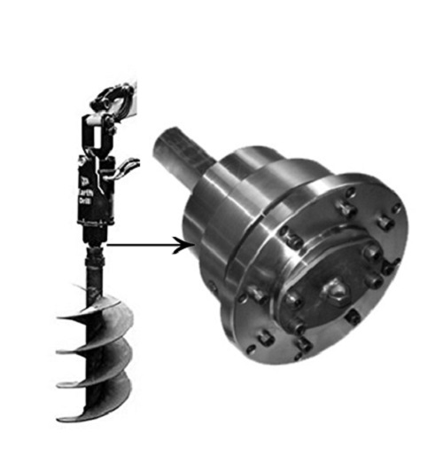
We have built planetary gear reducers in Ningbo for more than 20 years, and the same two questions arrive with almost every enquiry. What ratio do I need, and will the unit survive my load? Buyers usually get the first one right and the second one wrong.
This article separates them. The ratio is arithmetic, and you can do it on the back of a drawing. Load capacity is an engineering judgement about torque, duty cycle and side loads that the arithmetic will not give you.
What the reduction ratio actually tells you
A planetary gear reducer trades speed for torque. Feed it fast rotation at low torque, and it returns slow rotation at high torque. The reduction ratio is the exchange rate.
Three things follow from the ratio, and only three. Output speed drops by the ratio. Theoretical output torque rises by the ratio, less transmission losses. And the load the motor feels, reflected back through the gearbox, falls by roughly the square of the ratio. Nothing about ratio tells you whether the gear teeth, bearings or housing can hold the resulting torque.
That last point is where most selection errors start. A ratio of 100 does not make a small gearbox into a big one.
Three ways to calculate planetary gear reducer ratio
Method 1 — Speed definition
The simplest method, and the one to use when you already know your motor and your target output speed.
A hydraulic motor turning at 640 r/min driving an output that must run at 13.7 r/min needs a ratio of roughly 46.7. Read the table further down and you will find a stock unit at 46.8.
Method 2 — Tooth count (ring gear fixed)
Use this when you are designing the gear train rather than picking from a catalogue. In the standard configuration the ring gear is fixed to the housing, the sun gear is the input, and the planet carrier is the output.
A 20-tooth sun inside an 80-tooth ring gives i = 1 + 80/20 = 5. The planet gears do not appear in the formula. They transmit load and set torque capacity, but they do not change the ratio. For a standard train the planet tooth count follows from geometry: Zplanet = (Zring − Zsun) ÷ 2, which gives 30 teeth here.
This is also why single-stage planetary ratios have practical limits. Push the sun gear too small and you run out of tooth strength; push the ring too large and you lose the compact envelope that made you choose planetary in the first place.
Method 3 — Multi-stage reducers
Beyond a certain point you stack stages. The carrier of stage one drives the sun of stage two, and total ratio is the product of the stages.
Three stages of 5, 5 and 4 give a total of 100. That is how a multi-stage planetary reducer reaches ratios around 100 in a housing barely longer than a two-stage unit. The cost is efficiency, backlash and price, and all three accumulate stage by stage.
| Stages | Typical ratio band | Efficiency (compounded) | Trade-off |
|---|---|---|---|
| Single | Low | 97–98% | Best efficiency and lowest backlash, limited ratio |
| Two-stage | Medium | ≈ 94–96% | Balanced choice for most travel and swing drives |
| Three-stage | High | ≈ 91–94% | High ratio and torque, longer body, more backlash |
Single-stage efficiency of 97–98% is our published figure for CCMS planetary gear reducers. Multi-stage values are the compounded result of applying that figure per stage, and are indicative rather than a guaranteed rating for any specific model.
Reading ratio and torque from a real spec table
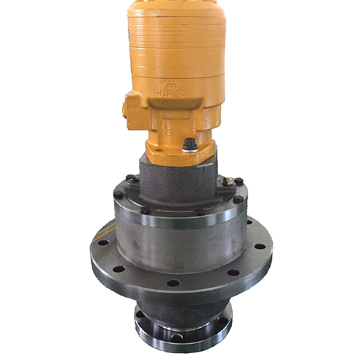
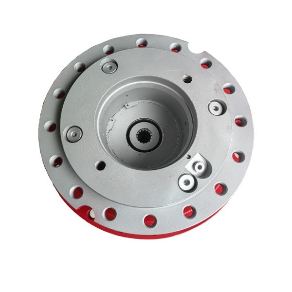
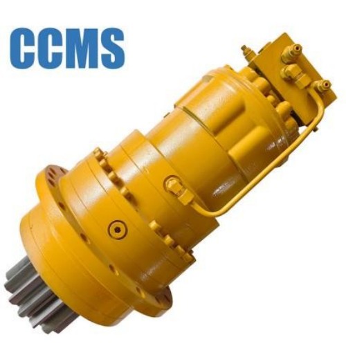
Formulas are easier to trust against real numbers. Below is the published parameter table for our 28000Nm Walk Planetary Gear Reducer family, a hydraulic planetary reducer built for travel and swing duty on heavy machinery.
| Model | Ratio | Output speed | Max. torque | Brake torque | Implied input speed |
|---|---|---|---|---|---|
| DHY2.1-6500-T2 | 46.8 | 13.7 r/min | 7,500 Nm | 9,800 Nm | ≈ 641 r/min |
| DHY2.1-9000-T2 | 36.1 | 9 r/min | 11,200 Nm | 13,500 Nm | ≈ 325 r/min |
| DHY2.1-9000A-T2 | 33.6 | 9.5 r/min | 11,200 Nm | 13,500 Nm | ≈ 319 r/min |
| DHY3.1-10000-T3 | 101.8 | 6.3 r/min | 12,500 Nm | 15,000 Nm | ≈ 641 r/min |
| DHY3.1-12500-T3 | 94.6 | 5.5 r/min | 15,500 Nm | 18,500 Nm | ≈ 520 r/min |
| DHY3.1-13000-T3 | 98.9 | 5 r/min | 16,000 Nm | 19,500 Nm | ≈ 495 r/min |
| DHY3.1-19000-T3 | 104.4 | 3 r/min | 23,000 Nm | 28,000 Nm | ≈ 313 r/min |
Model, ratio, output speed, max. torque and brake torque are published CCMS data. The implied input speed column is calculated here as ratio × output speed to demonstrate the method; it is not a rated parameter. Brake opening pressure 2.5–3 MPa, hydraulic motor options BMR-80 / BMR-100 / BMR-125 / BMR-160.
Two things are worth reading out of that table.
The T2 suffix marks two-stage units and T3 marks three-stage units, and the ratios confirm it: the T2 models sit between 33 and 47, the T3 models cluster around 95 to 105. The multiplication rule is visible in the product line itself.
The implied input speeds are not identical across rows. They range from about 313 to 641 r/min, because each model is quoted with a different hydraulic motor displacement and flow. This matters when you compare suppliers. A ratio quoted without its input condition is only half a specification, so ask what flow rate the output speed assumes.
Why ratio alone never gives you load capacity
Theoretical output torque is straightforward.
Take the DHY2.1-6500-T2 at ratio 46.8. Assume a motor delivering 160 Nm and a two-stage efficiency of about 0.94. The formula returns roughly 7,040 Nm, comfortably inside the 7,500 Nm rating.
Now assume 350 Nm at the input. The same formula returns about 15,400 Nm. The gearbox is rated for 7,500 Nm. The arithmetic is correct and the selection is wrong.
The formula has no upper limit. The gearbox does. Tout = Tin × i × η tells you what the input is capable of demanding, not what the output is permitted to deliver. Always check the calculated figure against the rated output torque, and size up if it exceeds the rating.
Load capacity is set by gear tooth strength, bearing life, carrier stiffness and housing rigidity. Those are fixed by the physical size of the unit. Multiple planet gears sharing the load is precisely why planetary designs carry more torque per unit of volume than parallel-shaft designs, and it is also why the rating stops where the metal stops.
Rated torque, peak torque and brake torque
Data sheets use several torque figures and they are not interchangeable. Comparing the wrong two across two suppliers is a common way to buy an undersized gearbox.
| Figure | What it means | How to use it |
|---|---|---|
| Rated / nominal torque | Torque the unit carries continuously for its design life | Size your steady-state working load against this |
| Max. / peak torque | Short-duration limit for starts, stops and shock | Check your worst transient against it, not your normal duty |
| Brake torque | Holding capacity of the integrated multi-disc brake | A parking and holding figure, never a working drive rating |
| Emergency / limit torque | Absolute survival limit before damage | A failure boundary, not a selection input |
Brake torque in our DHY table exceeds max. torque by design, because the brake must hold a stationary machine on a slope. It does not mean the unit can drive at that level.
Our DHY units use a hydraulically released multi-disc brake with an opening pressure of 2.5–3 MPa. Spring-applied and pressure-released, so loss of hydraulic pressure sets the brake rather than releasing it.
Service factor, duty cycle and the loads nobody lists
Two machines can present the same nominal torque and wear at completely different rates. What separates them is duty.
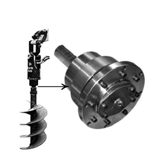
A conveyor drive running steadily for eight hours is a mild duty. An earth drilling planetary gear reducer that stalls in rock, reverses to free the auger and restarts under full pressure sees repeated shock loading. Same average torque, very different life. This is what a service factor accounts for: you multiply your calculated working torque by a factor reflecting shock, reversals, starts per hour and daily running time, then select against that higher number.
Three loads also sit outside the torque calculation entirely, and they are the ones we most often have to ask about after a customer has already chosen a ratio.
- Radial load. Side force on the output shaft or flange from sprockets, augers and overhung tooling. It determines output bearing life, and it is frequently the real limit rather than torque.
- Axial load. Thrust along the output axis, unavoidable in vertical drilling where the tool weight and crowd force both act downward.
- Thermal duty. Continuous operation at high input speed generates heat. Efficiency of 97% still means 3% of input power becomes heat in the oil.
We do not publish radial and axial load ratings on our product pages. Send us the mounting arrangement and we will provide the figures for the specific model, along with expected bearing life for your duty cycle.
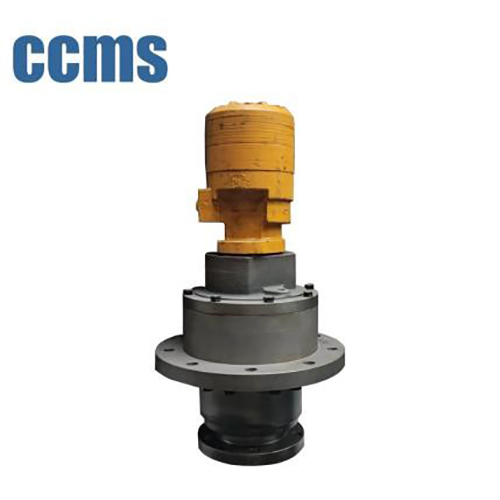
Worked selection example: an auger drive
A contractor needs an auger drive for photovoltaic pile foundations. The requirement: 40 r/min at the auger, 4,000 Nm continuous digging torque, frequent stalls in stony ground, roughly six hours of drilling per working day.
Step 1 — Establish input speed. The excavator auxiliary circuit and the chosen motor displacement give an input of about 640 r/min.
Step 2 — Calculate the ratio. i = 640 ÷ 40 = 16. A two-stage unit will cover this comfortably.
Step 3 — Apply a service factor. Frequent stalling in stone is shock duty, not smooth duty. Applying a factor of 1.5 to the 4,000 Nm working torque gives a design torque of 6,000 Nm.
Step 4 — Check against rated torque, not peak. Select a unit whose rated output torque is at or above 6,000 Nm. Selecting on peak torque here would leave nothing in reserve for the stalls that define this application.
Step 5 — Check radial and axial load. A vertical auger hangs its own weight plus crowd force on the output flange. Confirm the output bearing arrangement handles it before signing off.
Step 6 — Confirm the brake requirement. Decide whether the drive must hold the auger stationary under load, and specify brake torque separately from drive torque.
Steps 3 and 5 are the ones that get skipped. In our experience nearly every gearbox that comes back for warranty assessment was selected on nominal torque alone, with no service factor and no radial load check.
Five mistakes we see on incoming drawings
- Quoting a ratio with no input speed. A ratio is meaningless without the speed it acts on. State your motor speed or flow rate.
- Selecting on peak torque. Peak is a transient allowance. Continuous duty must be sized on rated torque.
- Treating brake torque as drive torque. The brake holds; it does not work.
- Ignoring efficiency in multi-stage units. Losses compound per stage, so a three-stage unit delivers noticeably less than the raw ratio suggests.
- Leaving out the duty cycle. Starts per hour, reversals and shock loading change the required size more than most buyers expect.
How we support ratio and load selection
We are a manufacturer, not a trading company, and our reducers are developed and produced in-house at our Ningbo facility. Our planetary gear reducer range covers walk planetary gear reducer units for travel and swing duty, earth drilling units for piling and auger work, and agriculture planetary gear reducer models for farm machinery.
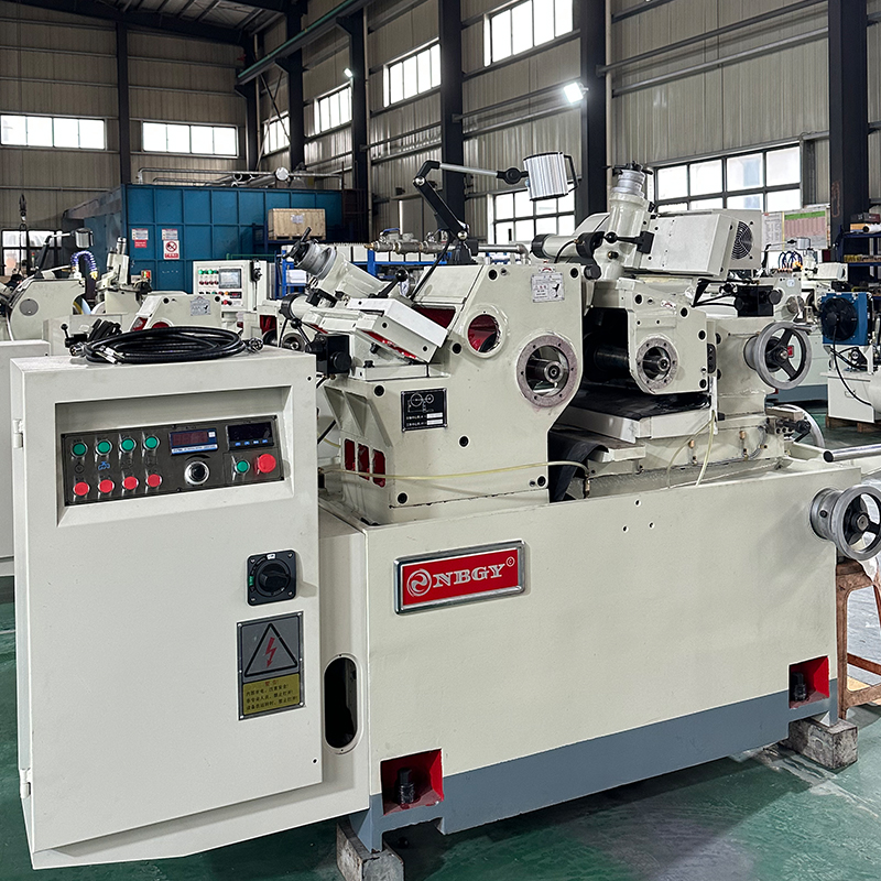
Core rotating parts are produced using closed-die forging, and machining is carried out on our own CNC equipment to a control accuracy of up to 0.01 mm. Our production is certified to ISO 9001 and every unit is subject to full inspection rather than sampling. You can review our equipment and inspection capability on our Our Strength page.
Our DHY-series units are supplied to domestic manufacturers including XCMG Group and exported to markets including Russia, Australia and India. If you are early in a design, send us the load case rather than a model number. Duty cycle, input flow, required output speed, mounting arrangement and any radial or axial load will let us confirm both the ratio and the size.
Related reading: Why Choose a Planetary Gear Reducer for High Torque?, How to Extend the Service Life of Planetary Gear Reducers?, How to Choose the Right Auger Drive and Drilling Gearbox: Functions, Types and Selection Guide.
Frequently Asked Questions
How do you calculate the reduction ratio of a planetary gear reducer?
There are two standard methods. From speed, divide input speed by output speed: i = n_in ÷ n_out. From gear geometry with the ring gear fixed, use i = 1 + Z_ring ÷ Z_sun. For a multi-stage unit, multiply the individual stage ratios together to get the total ratio.
Does a higher reduction ratio mean higher load capacity?
No. A higher ratio multiplies torque further, but the load capacity of the gearbox is fixed by gear tooth strength, bearing size, carrier stiffness and housing rigidity. Always compare your calculated output torque against the rated output torque on the data sheet, and select a larger unit if the calculation exceeds the rating.
What is the difference between rated torque, max torque and brake torque?
Rated torque is what the unit carries continuously for its design life. Max or peak torque is a short-duration limit for starts, stops and shock loads. Brake torque is the holding capacity of the integrated brake for parking a stationary machine, and it should never be used as a working drive rating.
What efficiency should I assume for a multi-stage planetary reducer?
Single-stage efficiency for our planetary gear reducers is 97 to 98 percent. Losses compound per stage, so a two-stage unit is typically around 94 to 96 percent and a three-stage unit around 91 to 94 percent. Use the compounded figure when calculating output torque for multi-stage units.
Why do two reducers with the same ratio have different output speeds?
Because output speed depends on input speed as well as ratio. In hydraulic planetary reducers the input speed is set by motor displacement and system flow rate, so two units with identical ratios will produce different output speeds if they are driven by different motors. Always ask which input condition a published output speed assumes.
What information do you need to recommend a planetary gear reducer?
Send us the required output speed, the continuous working torque, the input speed or hydraulic flow rate, the duty cycle including starts per hour and any shock or reversing loads, the mounting arrangement, and any radial or axial load on the output. With that we can confirm both the ratio and the frame size, and provide bearing life figures for your application.
Send us your load case
Our engineering team will confirm the ratio, frame size and brake specification for your application. We reply to technical enquiries within 24 hours.
Request a Selection Review