
The hole diameters pass. The inspection report is signed. Yet the bolts will not enter together, or the shaft turns freely until the housing is tightened. Repeating the same diameter checks may produce another passing report without explaining the assembly failure.
CNC machined parts can pass inspection but fail assembly when the inspection misses a specified relationship, the permitted component variations leave insufficient functional clearance, or the assembly uses a different condition from the one measured. Start by establishing what the report proves, then test the interface under controlled conditions. Do not tighten every tolerance or remake the batch before identifying which relationship needs correction.
1. What did the inspection actually prove?
A passing result applies to identified characteristics, parts, methods and conditions. First connect the report to the delivered part numbers, drawing revisions, sample identities and processing stage. An approved first article is evidence about that inspected sample; it is not a measurement record for every later component.
Separate these three paths before assigning a cause:
- A specified requirement was not evaluated correctly. A checked hole diameter does not establish compliance with a separate position requirement. This is incomplete verification, not proof of full drawing conformity.
- The components meet their requirements, but the design permits combinations that do not satisfy the assembly's function. The next task is to review the complete interface and its tolerance allocation.
- The inspected state differs from the assembled state. Finishing, support, fastening or temperature may change the relevant dimensions or relationships.
There can also be a simpler identity problem: a report for another revision, an unmatched mating component or mixed batches. Resolve that before analyzing small deviations. Our starting recommendation is to identify both sides of the interface, not just the component named in the complaint.
For CNC turning and milling parts for mechanical assembly, identify the surfaces that seat, locate, rotate or slide. Those functions determine which measurements are relevant.

2. Find the first point where assembly stops working
Record the first failed movement or seating condition. "Does not fit" is not specific enough: a shaft stopped at the entrance needs a different first check from a shaft that binds only after fastening.
| Observed symptom | Next check | Question the check addresses |
|---|---|---|
| Shaft stops at the bore entrance | Check finished mating sizes, entrance condition and visible obstructions. | Is the restriction local to the entry or present in the intended fit? |
| Shaft enters, then binds deeper inside | Evaluate size and form along the engagement length and the relationship between supporting bores. | Does the restriction occur at a particular depth or alignment? |
| Bolts enter separately but not as a complete set | Evaluate the full pattern with both parts located as intended. | Are individual checks concealing an incompatible pattern or locating relationship? |
| Housing rocks instead of seating | Examine contact faces, local raised material, debris and support conditions. | Is the interface obstructed, geometrically unsuitable or incorrectly supported? |
| Movement becomes tight after fastening | Compare seating and relevant geometry before and after the approved fastening sequence. | At what constraint change does the behavior begin? |
| Only certain component pairs fail | Record controlled cross-mating results and measure both components. | Does the pattern follow one component or a particular combination? |
These checks distinguish investigation paths; they do not establish root cause by themselves. Photograph the original condition and identify affected components before cleaning, removing a burr or attempting rework. Do not force parts together to obtain a passing trial: new damage can obscure the original restriction.
3. Cross-mate components before blaming one part
For assemblies that can be separated and reassembled without damage, a controlled pairing comparison can narrow the investigation. It is especially useful when one selected sample fits but interchangeable production components do not.
-
Identify each component
Label both sides of the interface with part identity, revision, batch and finish state. Keep the labels connected to the measurements and assembly observations.
-
Define the assembly condition
Use compatible revisions and the approved orientation, support, lubrication and fastening conditions. Define what counts as acceptable seating or movement before comparing pairs.
-
Record the selected combinations
Follow an agreed test plan and record each permitted pairing, including where resistance begins. Do not repeatedly assemble press fits, single-use fasteners or damage-sensitive interfaces without an approved method.
-
Compare the pattern
Look for results that follow one component, one mating component or only particular combinations. Treat inconsistent repeat results as a reason to examine the test conditions as well as the parts.
-
Verify the suspected relationship
Measure the relevant features on both sides using the specified references and state. Use those measurements to test the explanation before changing the drawing or production process.
| Housing | Mating part P1 | Mating part P2 | Mating part P3 |
|---|---|---|---|
| H1 | PASS | PASS | PASS |
| H2 | FAIL | FAIL | FAIL |
| H3 | PASS | PASS | FAIL |
In this example, investigate H2 because every tested pairing with it fails. Investigate the H3/P3 interface as well: its isolated failure may involve combined variation. Neither observation proves which dimension is responsible. If failures instead follow an entire column, focus first on that mating component.
A reference component is useful only when its identity, condition and relevant geometry are known. One unusually accommodating reference part can conceal a production interchangeability problem. The matrix is a diagnostic aid, not a statistically justified batch-release plan.
4. Calculate the clearance the assembly actually needs
A CNC-machined housing and spacer can both pass dimensional inspection while leaving insufficient clearance for the intended movement. Consider a hypothetical rigid assembly with a finished housing opening of 50.00 ± 0.05 mm and a spacer length of 49.85 ± 0.08 mm, both specified at 20°C. The nominal axial clearance is 0.15 mm, but the worst-case dimensional combination leaves only 49.95 − 49.93 = 0.02 mm. If the design requires at least 0.05 mm, that combination falls short by 0.03 mm despite both components meeting their individual size limits.
| Assumed specification | Baseline | Revised allocation |
|---|---|---|
| Housing opening, H | 50.00 ± 0.05 mm | 50.00 ± 0.03 mm |
| Spacer length, S | 49.85 ± 0.08 mm | 49.85 ± 0.04 mm |
| Minimum dimensional gap, H minimum − S maximum | 49.95 − 49.93 = 0.02 mm | 49.97 − 49.89 = 0.08 mm |
| Margin above the assumed 0.05 mm minimum | −0.03 mm | +0.03 mm |
Retaining the nominal dimensions while reducing the respective tolerances to ±0.03 mm and ±0.04 mm increases the calculated minimum clearance to 0.08 mm. This addresses the dimensional stack-up; surface geometry, datum relationships and deformation still require separate evaluation under the applicable drawing requirements. ASME Y14.5 provides the framework for specifying the relevant geometric relationships.
The financial decision should use an explicit cost threshold: if tighter machining and final-state verification add an assumed US$0.40 per assembly across 1,000 assemblies, the additional cost is US$400. At an assumed US$40 per attributable rework event, avoiding ten events recovers that expenditure on rework costs alone. Actual savings depend on demonstrated reductions in rework; neither tighter tolerances nor additional inspection establishes a service-life multiplier.
This example evaluates one axial size chain, with final dimensions at a common reference temperature and no deformation. It does not select a fit, validate a seal or account for thermal growth in service. The 0.05 mm requirement is an assumed design input, not an industry minimum.
Trace the dimensions that consume the required functional margin. Increasing nominal clearance, reallocating tolerances or changing the interface may each be options, subject to design approval. See the CNC machining tolerance guide for the distinction between size limits and geometric requirements.
5. Check references and redundant constraints
Identify what seats, locates and prevents rotation
A correct diameter does not establish that a bore axis has the required relationship to a mounting face or another bore. Review the drawing's applicable geometric controls and the datum features used to evaluate them. Do not substitute a convenient outside edge for a specified reference simply because it is easy to measure.
Manufacturing references need not be identical to drawing datums. A legitimate setup can use different locating features if the process produces the required relationships and the inspection evaluates the finished requirements correctly. The problem is uncontrolled transfer or inappropriate evaluation, not the existence of different setups.
Look for two locators competing to constrain the same motion
Two close-fitting round locators can make loading sensitive to differences in the distance between locating features. Making each hole more precise in isolation does not necessarily address that relationship. In its original round-and-diamond pin guidance, Carr Lane explains how a round pin provides two-axis location while a relieved diamond pin provides one-axis location, avoiding redundant constraint in the described fixture arrangement.
Any locator change needs approval for the actual application, including load transfer, repeatability and the permitted movement. Enlarging a locating hole simply to pass a trial assembly can remove a function the design depends on.
For components combining CNC milling and turning, show which face locates the part and which features control the full mating pattern. Local size checks should not stand in for that relationship.
6. Compare free, located and fastened conditions
If movement changes after fastening, record the first constraint change that produces the symptom. Possible investigation points include incomplete seating, local obstruction, support differences and elastic deformation. The observation alone does not distinguish them.
| Condition to compare, where applicable | Keep defined | Record |
|---|---|---|
| Supported without assembly fastening | Support points, orientation and measurement locations | Relevant geometry and initial movement |
| Located and seated, before final tightening | Locators, mating surfaces and approved assembly method | Whether the part seats and where resistance begins |
| Fastened as specified | Approved sequence, fastening conditions and the same measurement locations | Geometry or movement that changes after tightening |
| Released again, if permitted | A method that does not damage or invalidate the joint | Whether the change reverses or a permanent change remains |
Keep temperature, component identity and lubrication consistent unless one is the deliberate variable under investigation. Use the approved fastening instructions; a generic torque value cannot define the correct condition for every joint.
Do not automatically reject a flexible component because of its free-state shape if the requirements specify a restrained evaluation. Conversely, flattening a component in an inspection fixture may conceal a problem when the assembly does not provide that restraint. The specified condition determines the relevant comparison.
7. Inspect the finished interface, not an earlier version of it
Check the state after treatment
Confirm whether the report describes the part before or after finishing. The Aluminum Anodizers Council's technical FAQ explains that anodizing changes dimensions and that the change depends on process conditions and alloy; pretreatments such as etching also affect the result. Do not apply a universal coating-growth allowance to every bore, shaft or thread.
Identify the final mating dimensions and any approved masking. Compare both sides of the interface, not only the coated part. Our surface finish and treatment guide separates texture requirements from treatment and final dimensional acceptance.
Separate local obstructions from the underlying fit
An entrance burr or raised mark under a seating face can prevent assembly even when measurements elsewhere pass. Record its location before removal, then verify the affected edge and surrounding geometry after any authorized correction. The deburring and edge inspection guide explains why removing a burr must not consume a protected locating or sealing surface.
Compare temperature conditions
NIST's dimensional metrology guidance identifies 20°C as the standard dimensional reference temperature and discusses corrections and uncertainty when measuring at other temperatures. A reference temperature is not a requirement that every assembly operate at that temperature.
Where clearance is sensitive, record actual part temperatures and evaluate the mating materials under the relevant conditions. Do not combine readings from unknown temperatures or infer a working clearance from nominal room-temperature dimensions alone.
8. Read beyond the green PASS in the inspection report
A useful report lets another person reconstruct what was evaluated. Ask for the missing setup information before requesting another instrument or more decimal places.
| Evidence | What to establish |
|---|---|
| Identity and revision | The measured part, drawing, mating component and delivered batch correspond. |
| Requirement and actual result | Each result maps to a specific feature and its complete acceptance requirement. |
| Datums and alignment | The evaluation establishes the specified references rather than an unrelated convenient alignment. |
| Measurement coverage | The locations, extent and feature-evaluation method address the suspected relationship, not only accessible local points. |
| Support and restraint | The fixture and fastening state match the required evaluation condition. |
| Finish and temperature | The state measured is relevant to the delivered interface, with appropriate temperature treatment. |
| Uncertainty and decision rule | The result has suitable measurement capability and the agreed acceptance rule is applied consistently near limits. |
NIST's research on CMM traceability and uncertainty explains that calibration information must be combined with measurement-specific factors to establish task-specific uncertainty. A calibrated machine is not a guarantee that every program, fixture and feature evaluation has the same uncertainty.
When supplier and buyer results differ, compare the same identified components and conditions. Repeatedly selecting the lowest reading does not resolve the disagreement. See our CNC machining inspection and quality control guide for planning inspection stages and records.
9. Choose the correction that the evidence supports
Connect the finding to an approved action. "Make it tighter" is not a complete corrective instruction, and a new supplier cannot resolve an incompatible tolerance allocation merely by reproducing it more consistently.
| Finding | Action to evaluate | Verification before release |
|---|---|---|
| Measurements are not comparable | Reconcile identity, references, state and method; repeat the relevant evaluation. | Comparable results and the agreed acceptance decision |
| A recoverable local nonconformance is confirmed | Seek approval for defined rework, checking remaining geometry and protective treatment. | Corrected feature, affected adjacent requirements and function |
| Only selected pairs work | Investigate combined variation. Consider selective matching only if the requirements permit it. | Traceable approved pairs and any interchangeability or replacement restrictions |
| Requirements are met but functional margin is inadequate | Obtain an approved change to the interface, tolerance allocation or assembly requirements. | Revised requirements and relevant functional checks |
| Conforming recovery is unavailable | Remake under a corrected, approved production and verification plan. | Evidence that the new route addresses the established cause |
Before restarting production, define what evidence will demonstrate the correction. Include the relevant final finish, setup changes and mating-component variation. A single successful pair does not establish that the next batch is interchangeable. The verification scope should follow the application risk and agreed control plan, not a universal sample count.
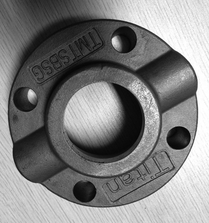
For repeat orders of turned and milled cast iron components, keep the affected feature requirements connected to the setup, finishing and final inspection instructions. The correction needs to survive the next production run, not just the reinspection of one selected component.
When discussing an assembly problem with CCMS Industrial, send both mating drawings and revisions, the final treatment requirements, affected pair identities, inspection results and a description of where the first restriction occurs. Contact Ningbo CCMS Industrial Co., Ltd. with those records so the technical discussion starts at the interface that failed.
10. Further questions about CNC parts assembly problems
Why does an approved sample fit while production parts do not?
The sample may represent only one combination of component variation, finish and assembly conditions. Later parts or mating components may differ within or outside their requirements. Compare their identities, actual measurements and final states before attributing the result to process drift or an inadequate tolerance allocation.
Can a successful trial assembly replace dimensional inspection?
Not automatically. A trial demonstrates behavior for the tested combination and conditions. It may not verify other drawing requirements or interchangeability across production. Use an approved functional test or gauge for its defined scope, alongside the other required inspections.
Does an assembly problem prove that the supplier made a bad part?
No. The cause may be an actual manufacturing nonconformance, incomplete verification, incompatible design allowances, a different mating revision or an assembly-condition mismatch. Establish the applicable requirements and examine both sides of the interface before assigning responsibility.
When is selective matching acceptable?
Only when the responsible parties approve it and the product requirements permit paired components rather than unrestricted interchangeability. Define identification, traceability and replacement restrictions. Selecting a pair that happens to fit does not make an otherwise nonconforming component acceptable.