
A smooth outside edge can hide an attached burr at the intersection of two bores. An aggressively rounded edge can create the opposite problem: the burr is gone, but so is part of a sealing land or locating surface. Deburring succeeds when it removes unwanted material while preserving the geometry the assembly needs.
For CNC machining deburring, identify the edges that matter, define the permissible material removal and select an inspection method that can reach each location. Treat a specified chamfer or radius, residual burr acceptance and particulate cleanliness as separate requirements. A general “deburr all edges” note cannot resolve all three.
1. Deburring, edge breaks and chamfers specify different outcomes
Deburring removes unwanted material left at an edge by machining. An edge break intentionally removes material around a theoretical sharp corner. A chamfer defines a particular geometric transition. One operation may achieve more than one outcome, but the inspection questions are different.
ISO 13715:2017 addresses indications and dimensions for edges of undefined shape. Its public scope distinguishes these from geometrically defined edges, such as a chamfer, which follow general dimensioning principles. Use a defined chamfer or radius where its shape matters to function; do not leave that shape to a general deburring instruction.
| Requirement | What the reader should establish | What it does not establish |
|---|---|---|
| Remove burrs | Which attached projections are unacceptable and how they will be detected | A particular chamfer size, radius or retained face width |
| Limit an edge break | Where removal is allowed and its permitted extent | An exact transition shape unless it is also specified |
| Produce a chamfer or radius | The required geometry, tolerance and location | Acceptance of a secondary burr at the new boundary |
| Meet a cleanliness requirement | Permitted contamination assessed by the agreed method | Absence of every attached burr or conformance of edge geometry |
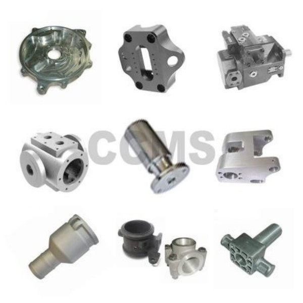
For parts combining CNC milling and turning, separate general handling edges from bore entries, mating faces and other functional boundaries. A single finishing instruction should not authorize the same removal everywhere.
2. Inspect the internal breakthrough, not just the outside hole
When one bore intersects another, the internal breakthrough creates a separate edge. Finishing the outside entrance does not demonstrate that the intersection has been deburred. The edge also follows the intersecting surfaces rather than a simple flat circle.
HEULE's crossbore tooling overview distinguishes different intersecting-bore applications, including customized solutions for multiple intersections and oil bores. The useful planning lesson is that access and intersection geometry have to be evaluated for the actual component. A tool that reaches one edge may not reach the next.
Use a section view or a numbered edge map to identify each required location. Include the entrance, exit, cross-hole rim and any recess that the tool or camera must pass. Record which side provides access and which areas remain out of view.
A borescope can help show an internal edge when the probe, view angle, lighting and focus are suitable. A partial view is incomplete evidence. If the inspection claims a numerical burr size, the method also needs a defined scale and sufficient measurement capability; an unscaled image establishes appearance, not a precise dimension.
3. Check how much functional surface remains after edge removal
A burr-free part can still be out of specification if deburring removes too much material. This is especially relevant where a narrow face must support a seal, contact a locating shoulder or provide a defined bearing area.
Consider a hypothetical flat land between two edges. The following values are assumed for the example, not recommended limits for a particular seal or component.
| Input | Assumed requirement | Measurement direction |
|---|---|---|
| Land width before edge removal, W | 1.40 ± 0.10 mm | Along the flat functional face |
| Left-edge loss, a | 0.20 mm maximum | Projected onto that same face |
| Right-edge loss, b | 0.25 mm maximum | Projected onto that same face |
| Required continuous flat land | 1.00 mm minimum | Between the two edge-removal boundaries |
Wmin = 1.40 − 0.10 = 1.30 mm
Minimum remaining flat land = Wmin − amax − bmax
= 1.30 − 0.20 − 0.25 = 0.85 mm
Both edge losses can meet their individual limits while the remaining land misses its 1.00 mm requirement by 0.15 mm. Check these requirements together. “More deburring” would make this particular problem worse.
Measure the projected losses along the face; do not substitute the sloping length of a chamfer. Actual seal suitability also depends on the specified surface geometry, finish, material and assembly. The calculation checks the available flat width only.
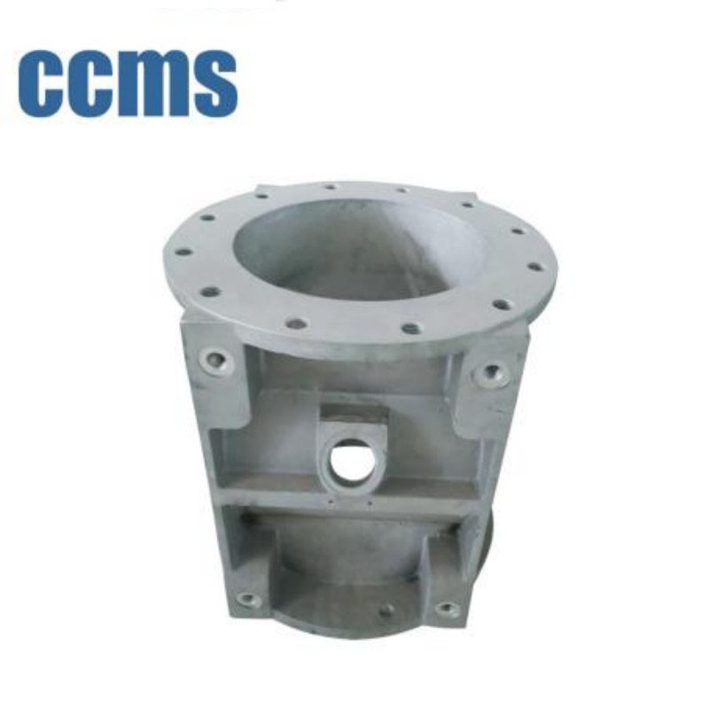
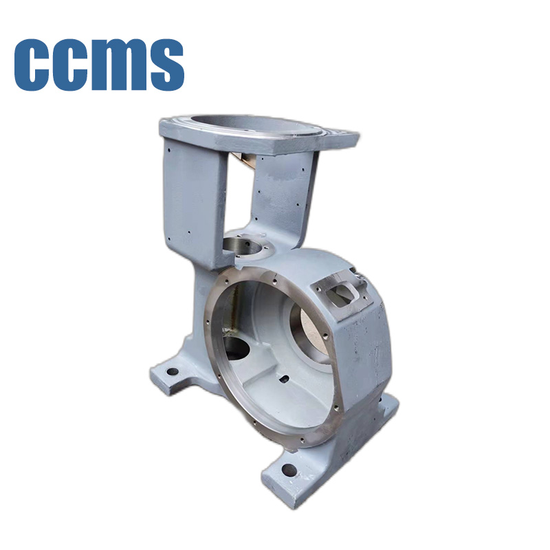
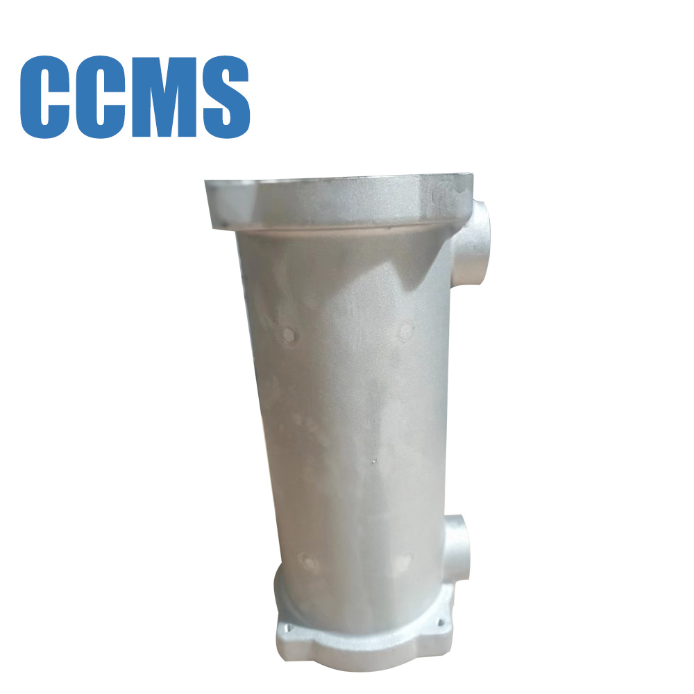
For machined cast aluminum bodies and heat-exchange components, identify the protected functional surfaces on the drawing instead of assuming all exposed boundaries can be rounded equally.
4. Choose the process around access and permitted removal
Review whether the proposed method can reach the required edge, remove the unwanted material and preserve adjacent features. Process names alone do not answer those questions.
| Approach to evaluate | Useful planning question | Check after processing |
|---|---|---|
| Targeted cutting or CNC edge machining | Can the tool reach the entire boundary with the required clearance? | Edge size, tool-access coverage and any new secondary burr |
| Manual bench deburring | How will the operator locate the edge and control removal consistently? | Protected dimensions, repeatable edge condition and complete coverage |
| Brush or abrasive treatment | Can the tool contact the burr root without exceeding adjacent surface limits? | Residual attachments, edge geometry and remaining media or debris |
| Mass finishing | Can the media reach the target and leave the cavities afterward? | Untreated internal locations, trapped media and overall edge removal |
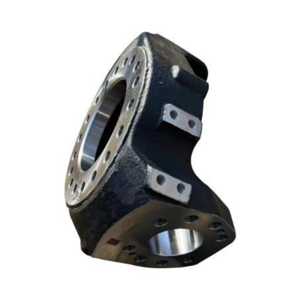
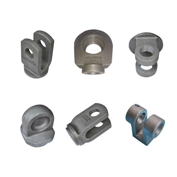
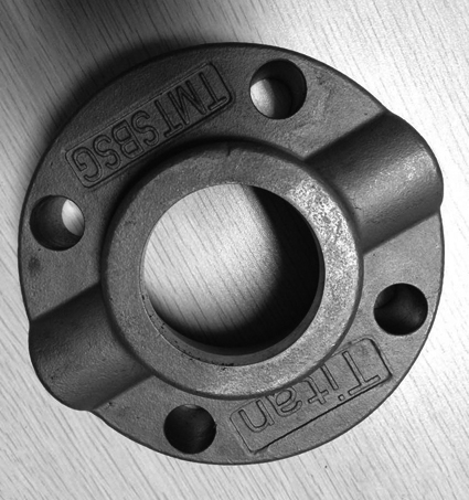
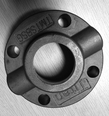
For cast iron parts with turned and milled features, review the actual material condition and edge geometry with the supplier. Do not transfer a process setting from a different alloy or part solely because the external shape looks similar.
Place the deburring step after the operations that can create the relevant burr. Drilling another intersecting hole, tapping or re-machining a feature can change an edge that was previously accepted. Agree any need for intermediate checks, then verify the final condition after the last relevant operation.
Connect cleaning, surface treatment and handling to that route. If rework occurs after the final cleaning step, reassess the affected cleanliness and surface checks. A signed record from an earlier stage does not describe the reworked condition.
5. Build an inspection plan around the feature, not the instrument name
For each controlled edge, connect the acceptance requirement to a location, method and recorded result. “Visual inspection” needs more detail when inspectors must agree on a small or partly concealed feature.
| Requirement | Evidence to define | A limit of that evidence |
|---|---|---|
| No unacceptable attached burr at an accessible edge | Identified edge, viewing directions, lighting and magnification where needed | A favorable view may miss a folded or concealed attachment |
| Specified chamfer, radius or retained land | A suitable optical, profile or dimensional measurement | A smooth appearance does not quantify the geometry |
| Internal cross-hole edge condition | A coverage map with suitable internal viewing or another agreed method | An unseen portion cannot be treated as inspected |
| Detached particulate contamination | The specified extraction, analysis and reporting method | A particle result does not prove every attached burr is absent |
| Lot acceptance | Sampling or full-inspection frequency, traceability and failed-result action | A first sample does not automatically accept later parts |
If a visual limit is used, agree how it is judged. Reference images should identify the location, viewing conditions and what makes a condition acceptable or unacceptable. A customer-approved reference can support consistent judgment, but it does not replace a separate numerical dimension where the drawing requires one.
Keep the initial finding before blending or cutting it away. An investigation record should identify the part revision, edge location, process stage and observed condition. Separate what is visible from a proposed cause or repair.
The CNC inspection and quality control guide covers the broader record. For edges near a tapped hole, the thread specification and inspection guide explains why thread fit, depth and position need their own evidence.
6. Deburring and technical cleanliness need separate acceptance
A burr is attached material; a loose chip or detached fragment is contamination. They can be related, but they need different evidence. Washing is not proof that every attached burr has been removed, and an acceptable edge photograph is not a particulate cleanliness test.
ISO 16232:2018 addresses methods for assessing particulate contamination on functionally relevant road-vehicle components and systems. Its scope excludes non-quantifiable visual or wipe assessments and does not set universal cleanliness limits for individual components. Where the project invokes this standard, define the part-specific requirement and test method rather than assuming the standard supplies a pass limit.
Keep the cleanliness requirement tied to the actual function and agreed standard. A limit for one hydraulic or automotive component should not be copied onto an unrelated part without evaluation. If oil films, residues or another contamination type matter, address them separately rather than treating a particulate result as coverage of everything.
Protection after cleaning also belongs in the process plan. Check whether handling, storage and packaging can introduce debris into the controlled areas. The surface finish and treatment guide is a useful companion when edge condition and later treatment must be coordinated.
7. Release a deburring requirement that can be verified
-
Map the controlled edges
Label outside edges, hole entrances and exits, internal intersections and protected surfaces on a drawing or section view. Identify the function and access for each location.
-
Define the allowed final condition
Specify the required edge geometry or permitted removal, residual burr acceptance and minimum retained functional dimensions. Separate local requirements from a general drawing note.
-
Check the process route
Confirm that the method reaches the required boundaries and follows the operations that create the burrs. Address cleaning, treatment and any later rework.
-
Prove inspection coverage
Assign a method to each requirement and show how internal edges are reached. Define viewing or measurement conditions, cleanliness testing where required, and the inspection frequency.
-
Close findings before batch release
Review the sample evidence, resolve uninspected locations and approve any repair or change. Release the controlled drawing, process and inspection instructions together.
A useful supplier review ends with an edge map and acceptance plan, not just a list of finishing processes. CCMS's machining services provide a starting point for discussing a part-specific route; the order should identify which edge and inspection requirements apply.
Further questions about deburring CNC machined parts
Can “break all sharp edges” replace a chamfer dimension?
Not where a specific chamfer size, angle or radius is required for function. A general edge-break instruction should not override a controlled local geometry or permit removal that violates a retained face or wall requirement.
Does a good surface roughness result prove that an edge is burr-free?
No. A roughness measurement describes the assessed surface and evaluation conditions. It does not automatically cover an edge outside that measurement or a hidden internal intersection. Inspect the controlled edge separately.
Is a borescope image enough to accept an internal edge?
It can support a defined visual acceptance method if the required area is fully covered and the image quality is adequate. It does not establish a precise burr dimension without suitable measurement capability, and it does not replace required cleanliness or dimensional checks.
Should a part be deburred again after a machining repair?
Review the features affected by the repair. If the operation creates or changes an edge, repeat the applicable edge checks and any affected cleaning, treatment or final inspection steps. Do not assume the earlier acceptance still covers the altered condition.
Discuss the edges on your part drawing
Send the drawing and relevant section views through the CCMS contact page. Identify hidden intersections, protected functional surfaces and required inspection evidence so those details are included in the machining review.