
A screw can enter a tapped hole and still fail to clamp the joint correctly. It may bottom out, engage too few complete threads or fit one hole while the rest of the bolt pattern is misplaced. A useful threaded-hole specification controls the thread itself, the available axial space and the inspection evidence separately.
For CNC machining threads, specify the thread system, size, pitch and tolerance class, then define the required complete-thread region, hole location and final condition after finishing. For a blind hole, also resolve tool clearance and the maximum permitted drilling envelope. Inspect thread fit, minor diameter, usable thread depth and position with methods suited to each characteristic.
1. Make the thread callout complete
Start by identifying the interface. A fastening thread, a pipe thread and a thread prepared for an insert can need different geometry, gages and acceptance rules. Similar outside diameters do not make them interchangeable.
For an illustrative metric fastening thread, M8 × 1.25 - 6H identifies an 8 mm nominal diameter, a 1.25 mm pitch and an internal-thread tolerance class. It does not state the hole's position, how far complete threads extend or how much load the joint can carry. The ISO 965-1:2026 tolerance-system overview covers ISO general-purpose metric M threads; use the standard and edition identified by the product requirements.
| Drawing information | What it resolves | A gap worth closing |
|---|---|---|
| Thread system, size, pitch and class | Which mating thread and tolerance system apply | "M8 hole" without a complete thread definition |
| Quantity and entry side | Which holes receive the thread and from which face | A symmetric model that hides the intended access side |
| Complete-thread depth or region | Where fully formed internal threads must exist | One depth value used for both threading and drilling |
| Entry chamfer or counterbore | Where usable threads begin relative to the finished face | A recessed entry silently included in engagement length |
| Location and orientation | How the threaded axis relates to the assembly datums | Acceptable thread fit with an incorrect bolt pattern |
| Finish and inspection condition | Whether requirements apply before or after treatment | Threads accepted before a coating changes the fit |
Write depth requirements so the starting face and endpoint are unambiguous. For a counterbored hole, distinguish the counterbore bottom from the external face. A model feature named "thread depth" is not enough if its definition differs between the CAD system, drawing and inspection plan.
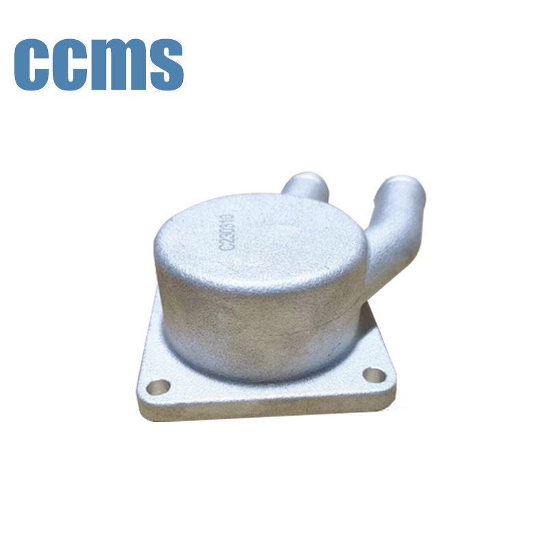
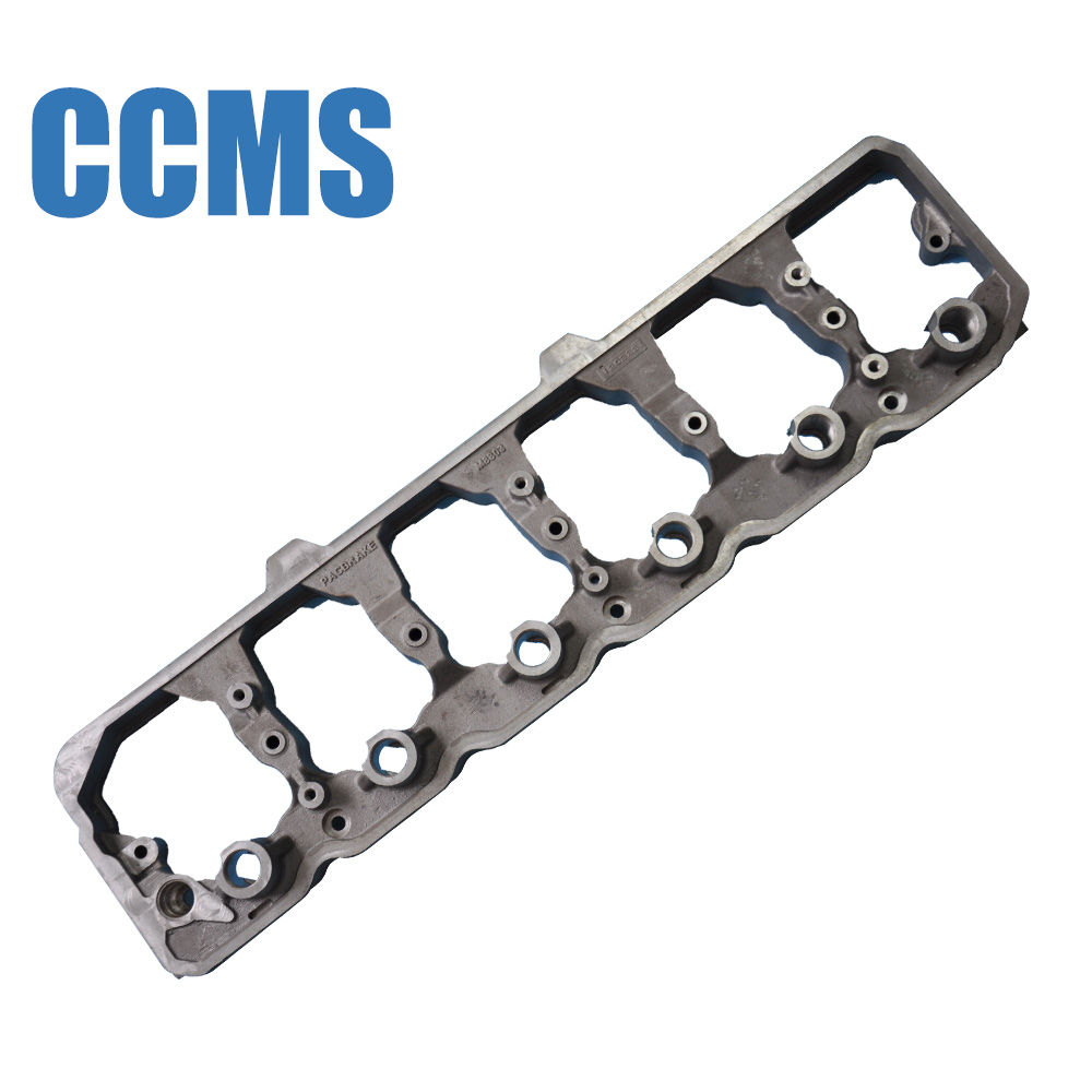
On products such as CCMS cast aluminum machining components, the thread interface belongs on the controlled part drawing. A product category or a photograph cannot select the mating thread standard.

2. A blind tapped hole has several different depths
Drilling provides space for the threading operation. It does not automatically create a usable thread down to the same endpoint. The entrance can contain a chamfer, the final internal turns can be incomplete, and a pointed drill leaves a tapered bottom.
The tap's lead is another separate feature: its chamfered teeth distribute the cutting action. A shorter lead can work nearer the bottom, but it does not eliminate the need to plan clearance. Sandvik Coromant's tap-selection guidance distinguishes chamfer designs according to the hole and available bottom clearance.
Ask for three separate answers in a blind-hole review: where complete threads begin and end; what clearance the selected tool needs; and how close any drilling may approach the opposite surface or internal passage. If a maximum drilling depth protects a thin wall, mark its reference and whether it includes the drill point.
The casting machining allowance guide is relevant when a cast passage or variable wall sits below the threaded boss. Adding drill depth without checking the casting envelope can solve a tooling problem and create a wall-thickness problem.
3. Check engagement and bottom clearance as a tolerance stack
Thread engagement is the axial overlap of usable mating threads in the assembled joint. It is not the nominal drilled depth or the length of screw projecting below a clamped plate.
Consider this hypothetical assembly, with all axial positions measured from the finished hole-entry face. The screw has usable external threads across the relevant region; its underhead runout remains outside the tapped hole.
| Input | Assumed value | What it represents |
|---|---|---|
| Underhead screw length, L | 20.0 ± 0.2 mm | Length to the physical screw tip |
| Clamped stack, G | 8.0 ± 0.3 mm | Distance from the screw bearing surface to the hole-entry face |
| Incomplete external thread near the tip, b | 0.7 mm maximum | Tip region excluded from complete-thread overlap |
| First complete internal thread, zs | 0.8 mm below the face | Entry region excluded from engagement |
| Last complete internal thread, ze | 13.0 mm below the face | End of the available complete internal threads |
| Earliest physical bottom obstruction, Zstop | 16.0 mm minimum | Assumed axial limit for contact with the screw tip |
| Required complete-thread overlap | 10.5 mm minimum | Hypothetical geometric requirement, not a strength recommendation |
The shortest screw combined with the thickest stack gives the least projection. Remove the incomplete tip and entry regions, and limit the overlap to the available internal-thread region.
Pmin = Lmin − Gmax = 19.8 − 8.3 = 11.5 mm
Emin = max[0, min(Pmin − bmax, ze) − zs]
= min(11.5 − 0.7, 13.0) − 0.8 = 10.0 mm
Pmax = Lmax − Gmin = 20.2 − 7.7 = 12.5 mm
Minimum tip clearance = Zstop,min − Pmax = 16.0 − 12.5 = 3.5 mm
The example clears the assumed bottom obstruction, but misses the required overlap by 0.5 mm. Looking only at the nominal 12.0 mm projection would hide that shortfall. Review screw length, stack tolerances and the usable thread region together before changing any one dimension. A production stack must also account for variation in the thread start and end positions and changes in stack height under assembly.
This calculation checks axial geometry. It does not establish stripping strength, preload or joint safety. NASA's Fastener Design Manual, section "Calculating Pullout Load for Threaded Hole" (PDF), treats tapped-hole pullout in relation to engagement and the threaded material's shear strength. A fixed multiple of nominal diameter is not a substitute for a joint-specific strength assessment.
4. The same finished thread can need different pre-hole preparation
A drill chart helps plan a process. The finished thread definition remains the acceptance requirement. The initial hole must suit the actual threading method, tool, material and required final geometry.
There is a useful documented comparison in OSG's A-XPF forming-tap catalogue, page 2 (PDF): its M6×1 through-hole example contrasts a 5.52 mm pre-hole for forming with a 5.00 mm pre-hole for cutting, under the stated test conditions. These are catalogue example values, not universal drill recommendations. They demonstrate why a cutting-tap drill chart cannot simply be carried over to a forming route.
| Route | Planning question | What must still be verified |
|---|---|---|
| Cut tapping | How will the tool manage chips and its lead at the end of the hole? | Pre-hole condition, full-thread depth and clearance for the chosen tap |
| Form tapping | Is the material suitable for forming, and is the pre-hole controlled for that tool? | Material ductility, lubrication, pre-hole size and finished thread acceptance |
| Thread milling | Can the tool and interpolation path reach the required thread region? | Tool access, runout region, programmed geometry and gage results |
For forming, Sandvik's guidance specifically identifies material ductility, precise drilled diameter and lubrication as prerequisites. A chip-free threading operation does not mean the drilled hole is free of debris.
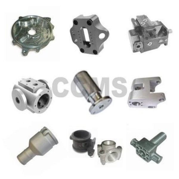
For parts combining CNC milling and turning, show the supplier the complete feature relationship rather than prescribing a process solely from the thread size. State any mandatory process restrictions separately.
5. Define the thread condition after finishing
A thread that fits before plating, coating or another treatment may not fit afterward. Specify the finished condition in which the mating and gaging requirements apply, including whether the threads are treated, masked or processed again afterward.
If masking is required, define its extent and what remains acceptable at the transition. If machining after a protective treatment is permitted, address the newly exposed surface. Do not let an unapproved thread-chasing operation become the automatic response to a tight finished hole.
Keep thread fit separate from surface texture and treatment requirements. The CNC surface finish guide explains that distinction for machined surfaces. The order should connect those requirements to the actual sequence rather than accepting unrelated reports from different stages.
6. GO/NO-GO thread fit is only part of inspection
A calibrated thread plug gage answers a defined thread-fit question. It does not locate the hole relative to the part's datums or determine the assembled joint's load capacity.
Glastonbury Southern Gage's explanation of thread plug gages distinguishes the GO member's functional checks from the NO-GO member's pitch-diameter check. It also notes that the internal thread's minor diameter requires a separate check. This is why "thread gage passed" is incomplete as the entire inspection record.
| Characteristic | Suitable evidence to plan | What not to infer |
|---|---|---|
| Thread identity and fit | Correct GO and NO-GO plug gages with the specified system and class | A nearby size or an ordinary assembly screw is an equivalent gage |
| Minor diameter | Appropriate plain limit gage or a suitable measurement method | Passing a thread plug also verifies the minor diameter |
| Complete-thread depth | A defined depth-verification method with gage lead, entry chamfer and reference face accounted for | Travel of an unqualified plug equals complete-thread length |
| Hole position and orientation | Measurement or functional verification tied to drawing datums | Each hole accepting a gage proves the whole pattern is correct |
| Cleanliness and final condition | Specified visual, cleaning and post-finish checks | A pre-finish fit result accepts the finished component |
| Traceability | Feature results, gage identity, calibration status, revision and lot reference | A generic inspection certificate identifies what was checked |
Use the acceptance rule for the specified thread standard and gage. Do not apply one remembered NO-GO turn count to every metric, Unified, short-length or special thread. Turn limits and exceptions need to be settled in the inspection instruction.
For a blind hole, verify that a plug is stopping because of the thread condition rather than contact with the hole bottom. A depth-marked or indicating gage still needs a defined relationship between its reference, lead geometry and the required complete-thread endpoint.

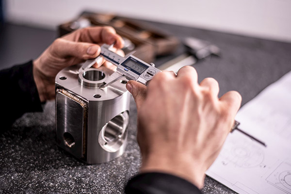
For inspection planning beyond the threaded feature, use the CNC machining inspection guide. Record results against the drawing characteristic, not just against the name of the measuring instrument.
7. When the screw fits poorly, investigate before reworking
| Observed problem | Check first | Avoid assuming |
|---|---|---|
| Screw stops before the joint closes | Projection, bottom clearance, usable thread length, debris and mating-thread identity | More tightening force will establish the intended clamp load |
| Parts fit before treatment but not afterward | Post-treatment thread condition, masking and the required inspection stage | Chasing the thread is automatically an approved repair |
| Individual holes pass but the assembly will not align | Pattern location, orientation, mating clearance and datum alignment | Thread class alone controls the bolt pattern |
| The GO plug stops in a blind hole | Gage selection, cleanliness, actual depth and possible bottom contact | The pitch diameter must be opened without further diagnosis |
Keep the initial condition available for review. Record which feature failed, at what assembly or processing stage, and with which mating part or gage. Reworking the first failed hole before documenting it can remove the evidence needed to distinguish a dimensional problem from a process or assembly problem.
8. Review a tapped-hole drawing before release
-
Identify the mating thread
Match the system, diameter, pitch, class, handedness where relevant, quantity and entry side to the intended mating part. Separate fastening threads from pipe threads and insert-preparation threads.
-
Close the axial geometry
Mark the reference face, first and last complete internal threads, maximum drilling envelope and assembly projection. Check the tolerance stack for engagement and bottom clearance.
-
Confirm the process and finished condition
Review the material, proposed threading route, pre-hole preparation, treatment sequence and any masking or post-treatment machining restrictions.
-
Assign evidence to each requirement
Define thread gaging, minor-diameter verification, complete-thread depth, location, cleanliness and final-condition checks. Specify the acceptance instructions and traceability needed.
-
Resolve exceptions before batch production
Approve the controlled drawing and inspection plan, close sample findings, and identify who can authorize a process change, repair or deviation.
A quotation can price a threaded hole accurately only when these requirements are visible. CCMS lists drilling and tapping among its machining services; the part drawing and agreed inspection plan define what is required for a specific order.
Practical questions about CNC machined threads
Can I inspect a tapped hole with the screw used in assembly?
An actual screw can help evaluate the intended assembly, but it is not a substitute for the specified dimensional inspection. Its own tolerances, wear, coating and tip geometry affect the result. Use the required gages and verify the assembly separately where needed.
Does a bottoming tap make complete threads all the way to the bottom?
No. A bottoming tap still has lead geometry and needs clearance appropriate to the tool and hole. Define the complete-thread endpoint separately from drilling depth, and verify that the chosen process can reach it without violating the permitted drilling envelope.
Should every tapped hole be inspected with GO and NO-GO gages?
The inspection plan should define the required checks and their frequency according to the product requirements and process risk. A sampling plan and a requirement for every hole to be checked are different instructions. State the lot definition, acceptance rules and response to a failed result.
Can a threaded insert be added if the original tapped hole fails?
Only when the product requirements permit an approved insert repair or design change. The insert may require different preparation, installation clearance and inspection. Check the remaining wall, engagement, surrounding features and final assembly requirements before authorizing it.
Have a drawing with threaded features?
Send the drawing, mating-thread details, material and final surface condition through the CCMS contact page. Include critical engagement, depth and inspection requirements so the process review covers the finished assembly as well as the machining operation.